The Pull-out Behavior of Lattice Girders in Composite Concrete Floors
In 2017, the newly built parking garage at Eindhoven Airport collapsed. This graduation project is part of the research after the collapse. In previous research, the different failure modes of composite concrete floors have been investigated. Pull-out failure of the anchorage of the lattice girder from the precast slab, however, remains unclear. The research consists of a finite element analysis and an experimental phase.
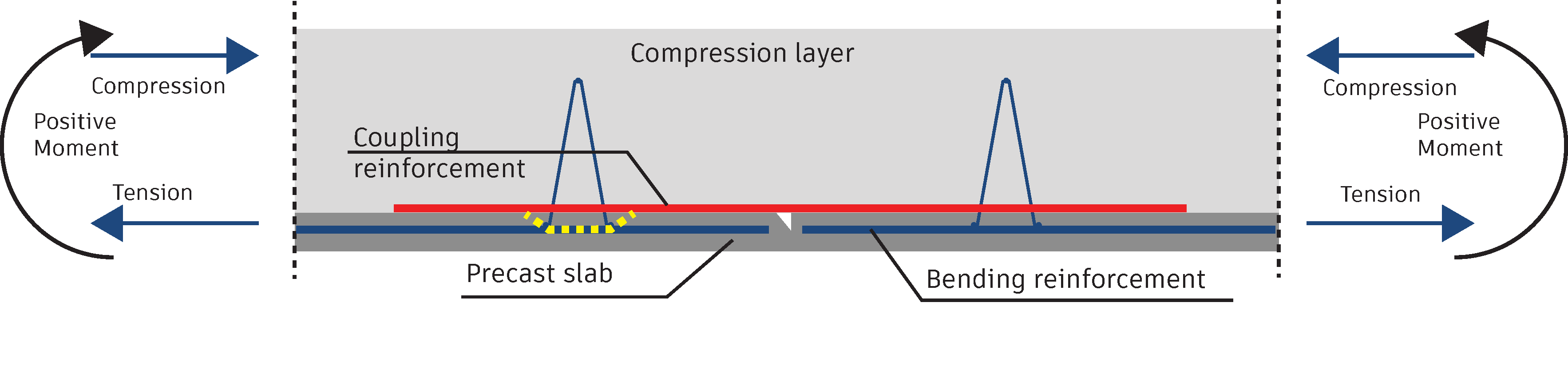
Figure 1: Pull-out failure of a lattice girder near a critical detail in composite concrete floors.
Layouts of floor slabs exist where one slab’s span is insufficient or the floor spans in two directions [1]. In these configurations, a moment has to be transferred between the precast slabs containing the bending reinforcement mesh through the in-situ layer, see Figure 1. Around this critical detail, three failure modes occur: yielding of the coupling reinforcement, failure of the interface between the two layers, and pull-out failure of the lattice girder from the slab, see Figure 1. The main parameter supposed to positively influence the strength of the casted lattice girder connections is the embedment depth, the depth to which the lattice girder is inserted into the slab.
Analyzing the described situation, lattice girders present near a so-called critical detail. It becomes clear that the lattice girder is subject to three forces: a shear force, a tensile force, and a bending moment. It is unclear which force has which influence on the failure of the lattice girder. Pure vertical tension will result in pull-out failure. The addition of shear force and the combination of the moment and shear force will also influence the resistance of the anchorage. The surface of the steel lattice girder’s diagonals crossing the interface is smooth: most of the anchorage is likely achieved through mechanical interlock instead of bonding with the surrounding concrete, which is usual for reinforcement.
To test the failure behavior of this detail, a test setup is created. In order to determine the magnitude, locations, and directions of the forces, an existing finite element model is used [2]. Based on the analysis of different geometries, a test setup is derived. Twelve specimens are tested with four different insertion depths of the lattice girders into the slabs. Partly, the specimens are precast; the top layer is cast in the Laboratory for SED. The interface between the two layers of concrete is connected with a roughness similar to composite concrete floors. Four threaded bars are present in the top layer of concrete to which two plates are connected to transfer the forces from one single jack to the concrete, see Figure 2. It is expected that with a higher insertion depth, the resistance of the lattice girder will increase. On some specimens, strain gages are attached to the diagonals before casting. These cast-in strain gages are used to measure a strain-, and thus stress difference in the diagonals to determine the influence of the bending moment on the resistance.

(a)

(b)
Figure 2: (a) Schematic overview of the test setup and (b) Specimen.
References
[1] Adviesbureau Hageman. (2019). Onderzoek constructieve veiligheid breedplaatvloeren in bestaande utiliteitsgebouw.
[2] Otterspoor, P.M.L.M. (2022). Experimental and Numerical Validation of an Adjusted Design and Calculation Approach of Mid-Span Joints in Composite Concrete Floors.