Evaluation of fatigue cracks in metals starting from the root of a weld
The assignment is to determine the SIF for weld root cracks using the FEM
Introduction and aim
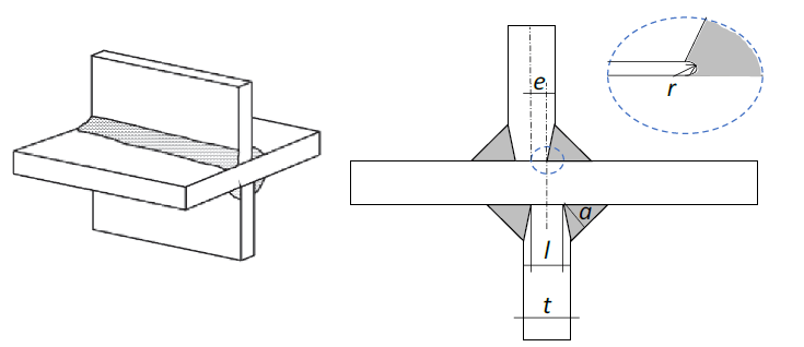
Fatigue cracks caused by fluctuating loads initiate from initial defects in the material. Welded joints are full of those initial defects, resulting from the welding process. In many cases, multiple initial fatigue cracks initiate and then they coalesce to form one dominant fatigue crack. The growth rate of fatigue cracks – i.e. the fatigue life of a propagating crack – can be simulated using fracture mechanics. Such a simulation requires data on the Stress Intensity Factor (SIF), which is a measure for the stress state in the vicinity of a crack. The SIF depends on the far-field stress, the geometry, and the fatigue crack size. The SIF can be determined with the Finite Element Method (FEM). Analytical formulae are available for cracks starting at the weld toe, but not for cracks starting from the weld root (Fig. 1). The assignment is to determine the SIF for weld root cracks using the FEM.
Goal of the study
The study consists of the following steps:
- Make a parametric model with the FEM of a cruciform joint (Fig. 3) with weld root cracks. The parameters are the crack depth, the crack length, the plate thickness t, the weld throat a, the unfused land l, the root radius r, and the eccentricity e.
- Carry out an analysis for the SIF with the parametric model. Tabulate the SIF values.
- Carry out fracture mechanics simulations for initial cracks with various sizes. Determine the fatigue life in each simulation.
- In reality, multiple cracks develop at the same time in such joints (Fig. 3). Modify the parametric model so that multiple initial cracks with various sizes can be implemented in such a way that they may coalesce at growth (Fig. 4). A new parameter will be included at this step, the distance between two successive initial cracks (See distance S in Fig.4)
- Carry out fracture mechanics simulations for multiple initial cracks. Compare the fatigue life with those of step 3, in order to estimate the difference between a single versus multiple initial cracks.
Interested? Please contact prof.dr.ir. Johan Maljaars at J.Maljaars@tue.nl
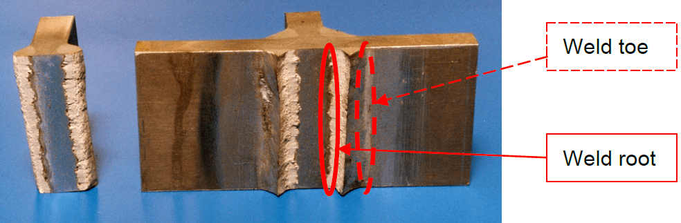
Fig. 1. Specimen failed through fatigue initiated from the toe
Fig. 2. Cruciform joint
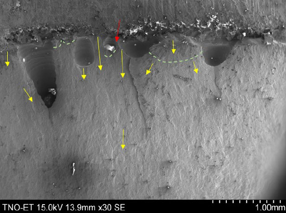
Fig. 3. Initiation locations and propagation direction of fatigue cracks
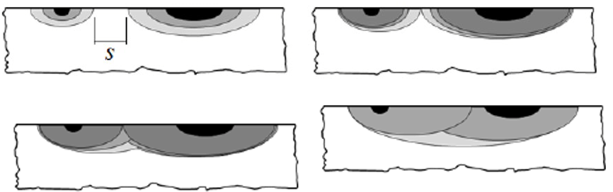
Fig. 4. Coalescence of cracks