Allegiant Stadium
Allegiant Stadium is the fastest designed and constructed US football stadium of its size. From concept design to completion in only 40 months. As the new home of the Las Vegas Raiders, Allegiant Stadium is an iconic addition to the Las Vegas Strip. With 65,000 seats that can be expanded by 7,000 additional seats during major events, it is the largest entertainment venue in Las Vegas. Allegiant Stadium will be used for a variety of events beyond Raiders football games, and it has been designed to be flexible so that it can be adapted trom professional and college football games to non-sporting events such as concerts. lt features walls that open to views of the Las Vegas Strip, as well as a translucent cable-truss supported roof.
Allegiant Stadium is one of two domed stadiums in the US with a retractable natural grass playing field, a musthave element for the Raiders organization. The stadium was designed by Manica Architecture and HNTB is the architect of record. The general contractor was a Joint Venture between Mortensen and McCarthy (MMcJV), and CAA Icon was the project manager. Arup joined this team as the structural engineer of record and helped bring this unique stadium to life.
The fast-track Design-BuiId delivery method was essential in completing the stadium respecting the budget and on time for the start of the 2020/21 football season. Working together with the Clark County Department of Building and Fire Prevention, Arup implemented a collaborative review and approach that allowed MMcJV to start work on the foundations and concrete bowl structure four months prior to permitting the steel and cable structure above.
At the same time, Arup issued an early steel mill order and detailing sequences to the fabricator to ensure the structural steel was ready to start erection the day the final structural permit was pulled.
Bowl and concourse structure
The Bowl and Con course refers to the structure supporting all stands/seats, concession, lounges, home and away team facilities in the lower levels, and all transportation elements such as elevators, escalators, and a major ramp, allowing vehicle access to all levels. lt has been segmented into four independent structures for thermal expansion control. The bowl structures are also separated from the Vessel structure for lateral forces. The exterior column line of the Concourse is shared with the Vessel structure on all levels using complicated slide-bearing details, which allow independent lateral movement, but provide gravity support including uplift restrained in certain locations. The Bowl and Concourse structures are made of reinforced concrete up to the second floor and steel structure above. The lateral system relies on ordinary reinforced concrete shear walls. The seating units are precast concrete and supported by structural rakes. In-plane steel braces in a chevron arrangement create a diaphragm, tie the seating units together, and safely deliver the lateral forces into the shear walls. We intentionally incorporated the diaphragm bracing into the steel frame to remove the need for temporary braces and, by doing so, decouple the precast design and erection process from the supporting frame.
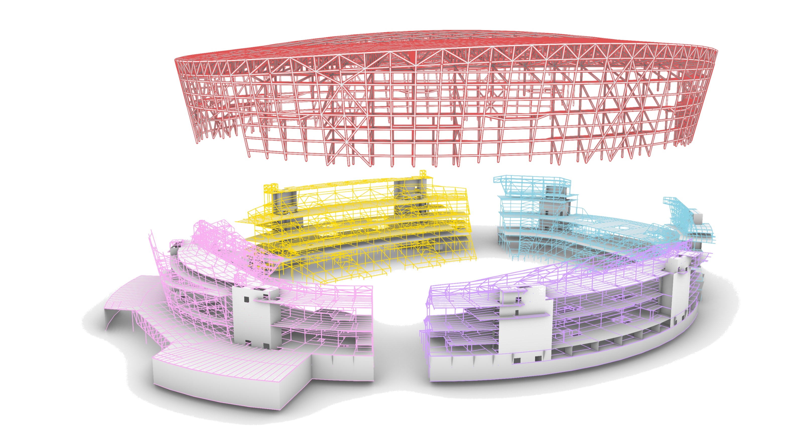
Figure 1: Structural separation of the roof and the four independent bowl structures
Steel & cable truss roof
Realizing the architectural vision, while meeting the exterior skin performance requirements, Arup incorporated a lightweight and delicate cable truss roof. The fully enclosed ETFE pillow roof is supported by a 20 meters deep cable truss roof within a cantilevered compression ring.
This type of structure typically requires significantly more precise construction tolerances and methods to achieve. To save time and money, Arup implemented a unique design using 54 field adjustable cable end connections. These connections allowed enough tolerances to install cut-to-length cables without excessive and expensive compression ring tolerances and were able to accommodate the construction of the roof structure through staged construction with no shoring of the canopy.
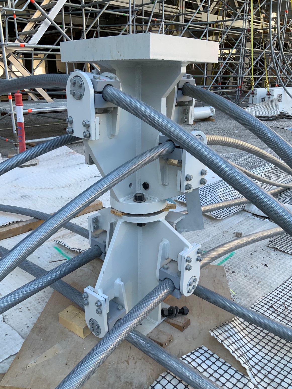
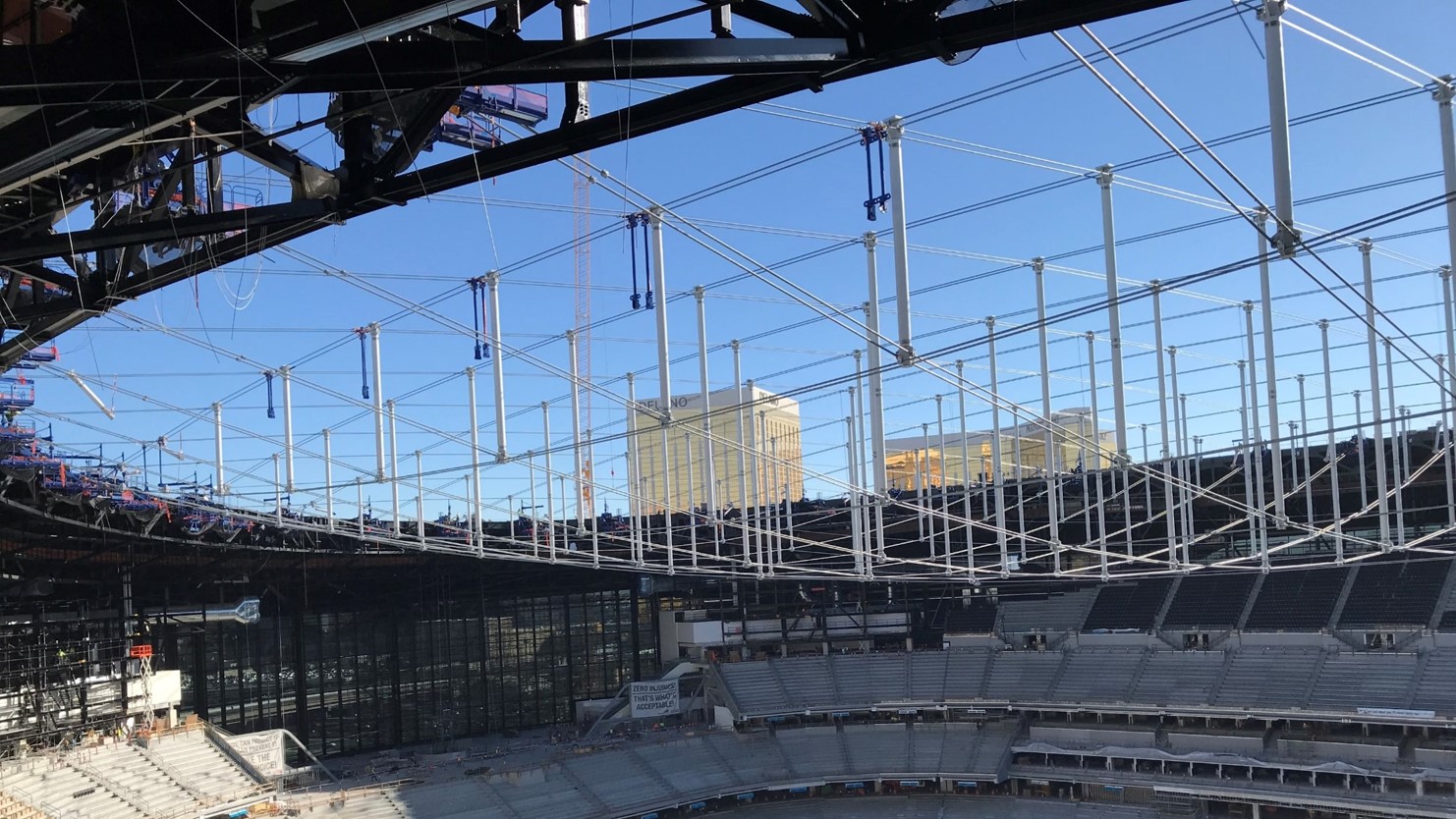
Figure 2: Cable truss roof and structural node roof
Movable structures
Achieving a comfortable atmosphere inside the stadium for players and spectators, is a major undertaking that requires a fully enclosed stadium and a translucent roof. These conditions, however, do not allow for the sustained growth of natural grass, which is one of the key requirements for the owner. The solution is a pitch which can be moved to an outside parking position to have unobstructed sunshine exposure between game days. The steel-concrete composite cable trough that carries the pitch, including all utilities, is supported on thirteen rails. The pitch can be moved via computer-controlled electric motors and requires a 70 meters wide opening under the south end zone stands. Seven 70 meters long transfer trusses support the south end stands, including the respective stadium vessel and roof structure.
Retractable columns located at the third points of each truss, make space when the pitch is moved and engage through a hydraulic mechanism when the truss is back in playing position. Through these columns, the trusses gain enough stiffness to support the fully occupied south end of the stadium while maintaining an acceptable vibration performance on the stands.
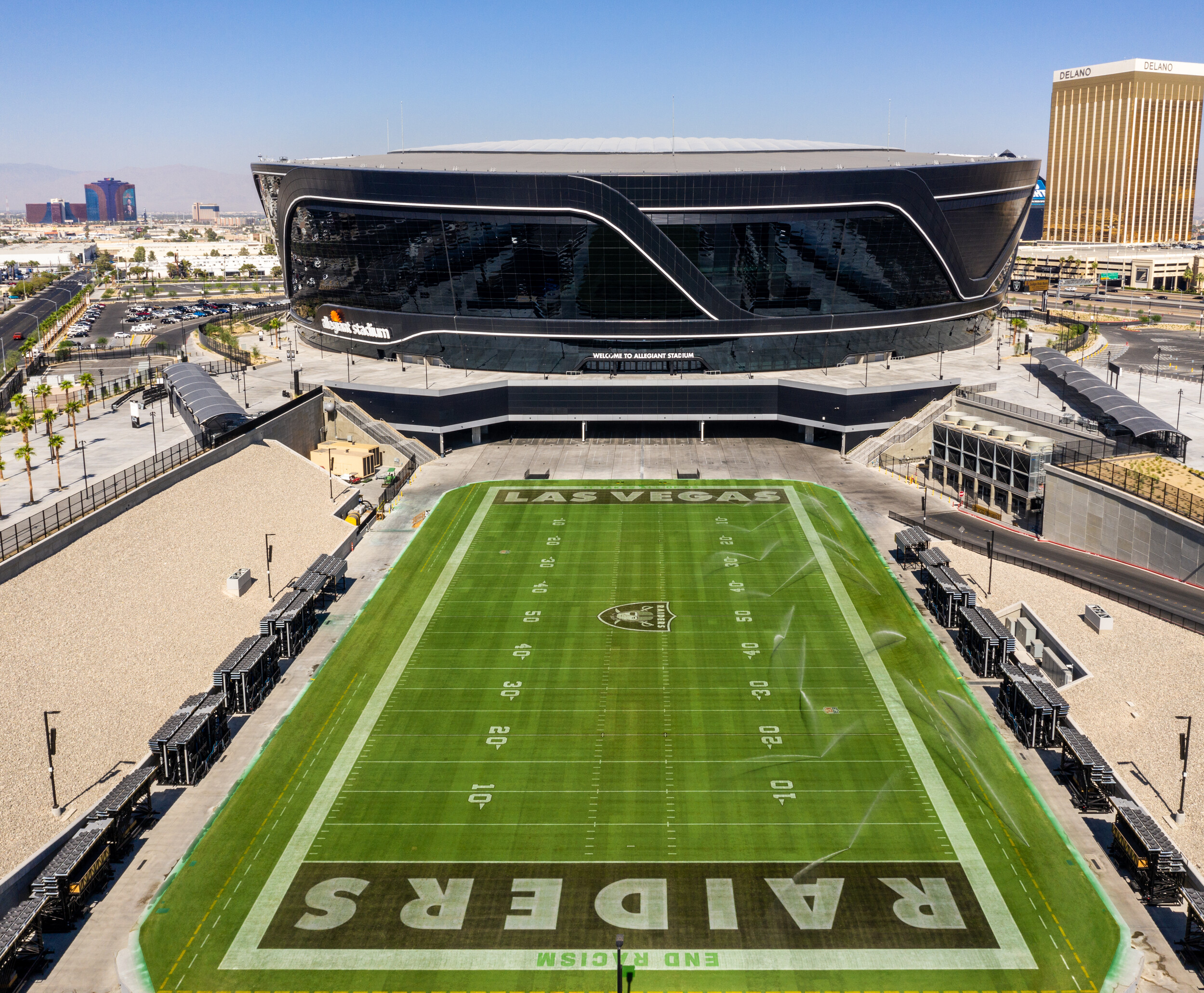
Figure 3: Movable feeld tray in exterior position
Foundations
The ground conditions were challenging due to the caliche layer present at the stadium site which required special excavation using explosives. The foundation system consists of hollow stem auger cast piles. These pi les were grouped using pile caps under the shear walls and exterior wall structures. Lower load columns were supported using single piles.
We designed all piles and the attaching pile caps to the minimum code required construction eccentricities. To activate all pi les under the stadium to resist lateral loads, we tied the piles together using the slab-on-grade and supplemented the slab on grade diaphragm with grade beams at high load areas. The slab on grade and the grade beams also provided the code required lateral tie forces and helped to accommodate larger pile tolerances where needed.
Foundations for smaller gravity loads were supported on shallow foundations. Also, here we made sure that the resulting shallow foundations deformation was compatible with the deep foundations deformations. The auger cast piles were load-tested for each quadrant of the stadium to gain confidence in their vertical load capacities and deformation behavior. When needed, we adjusted the foundation design to accommodate the test results. Overall, the foundation system allowed a fasttrack construction and was very cost-effective.
Construction led design
Designing and constructing a large scale stadium in record time needed strategies to parallelize and speed up workflows, rethinking standard practices in 3D documentation.
1. The structural separation concept does not only consider structural requirements, but it also facilitates the concurrent erection of major portions of the main structure. For example, the separation concept allowed the vessel and roof structure to be constructed independently of the bowl structure.
2. Additionally, this concept allowed Arup to split the structural permittin into four permit packages and helped in building confidence with the reviewing authorities.
3. The current industry standard is to deliver 2D drawings and a Revit model to the steel contractor, who will build a 3D Tekla model for scratch for fabrication and erection. A sequentia! and timeconsuming process. Arup delivered a detailed design of Tekla main steel model, resulting in significant time savings. For continuous architectural coordination, we automatically constructed a native Revit model from the Tekla steel model using our automation tools.
4. Database-driven automation processes and cloud computing allowed us to handle the large amount of data and models, resulting in the following benefits:
a) Synchronized, parallel workflows i.e. multiple teams can work with the same set of data.
b) Use of our in-house built design and post processing tools which are agnostic to the analysis software used.
c) Combination results and designing elements using farces from separated models. This allowed us to respond quicker to changes or client requests.
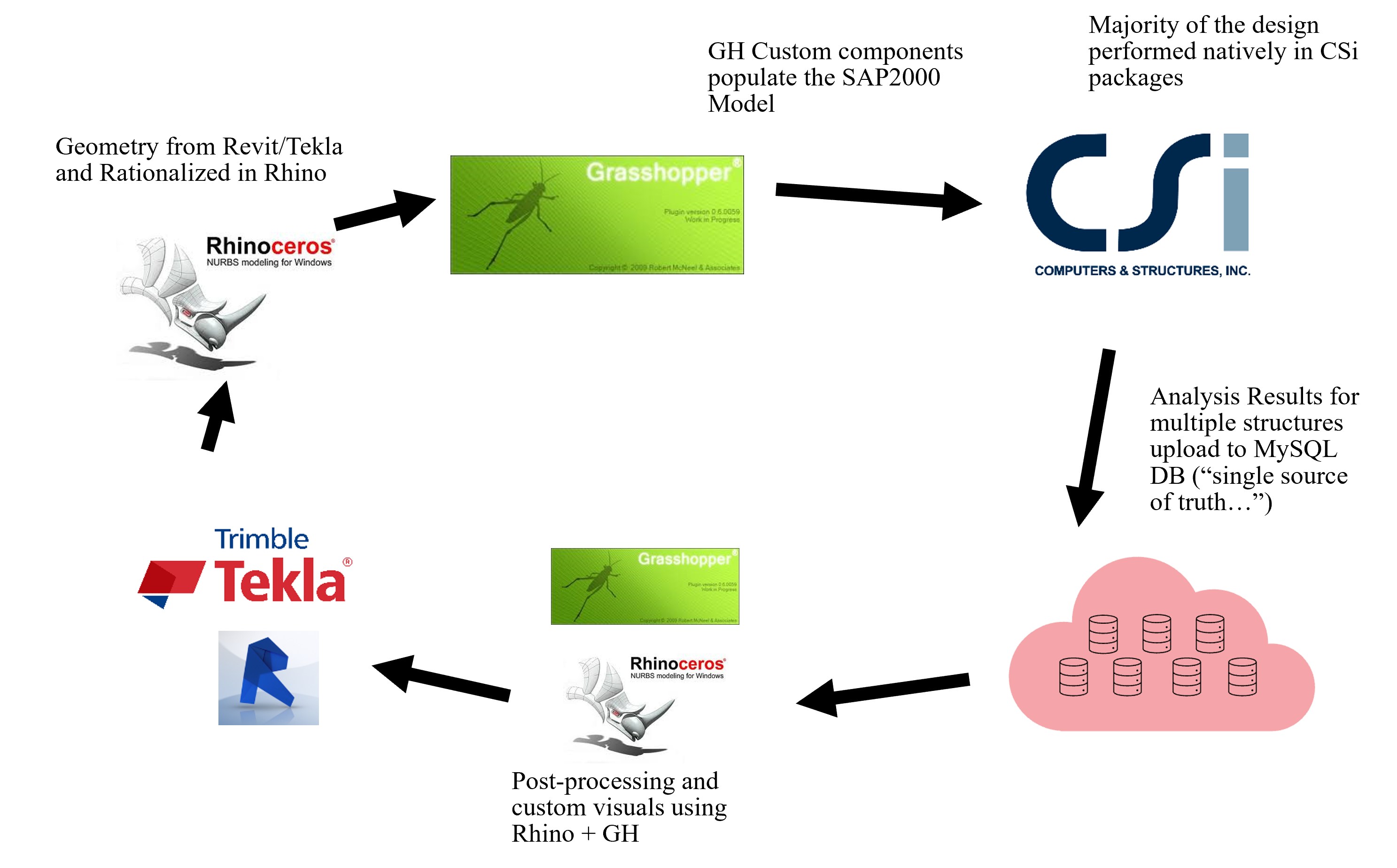
Figure 4: Data driven automation process and cloud computing
We would like to thank the Owner, the JV, and our client HNTB for the opportunity and support. We are proud to be part of this team and to have contributed to the success of the project. The delivery of such a fast track design was only possible by leveraging our global network of structural engineers and experts.