Arachnid Design
The Institute for Computational Design (ICD) and the Institute of Building Structures and Structural Design (ITKE), both from the University of Stuttgart in Germany, came together to create a pavilion in 2014-2015. It was developed at the intersection of the two institute's research fi elds and was realized, including the design and research phase, in one and a half year. Their aim for this innovative pavilion was rethinking our construction method by looking at nature and using this as a starting point for the construction of this structure. What can we learn from nature? Is a computer able to construct in an effi cient way without interfering during the actual construction time?
For the 2014-2015 research pavilion, the interdisciplinary team got inspired by the so-called Agyroneda Aquatic, the water spider. This spider lives almost its entire life under the water surface and will only briefl y surface to replenish oxygen. To breathe, the spider creates an interesting diving bell. First, the spider builds a horizontal sheet web under which an air bubble is placed.
In the next steps, the bubble is reinforced by the spider in a hierarchical arrangement of fi bers from within. It can, of course, withstand water pressure and it can even withstand mechanical stresses, such as changing water currents, to provide a safe and stable habitat for the spider (Figure 1).

Figure 1: Water bubble reinforced with spider web
The materials in which the pavilion was constructed where carbon fi ber for the structure and EFTE polymer. The carbon fi ber was chosen for its large stiff ness. This would reduce the amount of fi bers needed resulting in more transparent pavilion. The EFTE polymer was chosen due to its suitability as a pneumatic formwork and a minimal plastic deformation during the printing process. In addition to being the formwork during construction time, the polymer would also function as the skin of the pavilion, making it air and water tight. By allowing the formwork to serve as crucial part of the building itself, the waste during construction time as reduced to a minimum. To create a bond between the carbon fi bers and the EFTE pneumatic formwork, an adhesive composite was also applied by the robot. Working from the inside, the robot was able to print the carbon fi bers onto the membrane on the places where it was needed according to a fi nite element analysis executed by the University of Stuttgart. The shell, initially supported by air pressure, gradually stiff ened by the application of the carbon fi bers. Before the construction started, the computational design generated a shell geometry and main fi ber bundle location, regarding the structural and construction limitations. The best options for the placement of the main reinforcement was analyzed in the fi nite element analysis, creating a clear distinction between main reinforcement and reinforcement needed between the main carbon fi ber bundles (Figure 2).

Figure 2: The robot's printing process
By applying this main reinforcement according to the plan as was computed, which was needed to provide stiff ness for the pneumatic structure, a changed stiff ness of the bubble was created. These changes resulted in deformations during fi ber placement. To control these changes and let the robot adapt to the altered printing surface, an embedded sensor system was integrated into the robot which recorded the current position of the robot and the contact force between the robot and the EFTE polymer.
This development allows constant feedback between the production conditions, the EFTE polymer in this case, and the robot which was coded to create something in a 3D and static, environment (Figure 3).

Figure 3: The processing of the robot, which makes it possible for the robot to interact on alterting situations
Especially this technique, very similar to the spider sensing the bubble and constructing wires, creates new possibilities for adaptive robotic construction processes. It is needless to say that the technical development of the robot, with its construction limits, and the structural limits of the carbon fi bers in combination with the EFTE polymer form an integral part of the architectural design process. The additive process has not only allowed stress-oriented placement of the fi ber composite material, it also minimized the construction waste since the material is placed on the exact location where it is needed. Where 3D concrete printers are already an innovative construction method, replacing manual labor by machines, this process goes a step further. The machine can communicate with the engineers, by providing valuable information of, in this case, the formwork. In addition, it can also print carbon fi bers by itself on places where it is needed. However, the actual threshold of where the material is needed, is still programmed by the engineers.
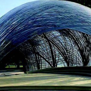
The 0.2 millimeters-thick EFTE fi lm spans maximum 25 centimeters between the bundles of carbon fi bers, which on their turn range in diameter from 1 millimeter to 2 centimeters. The total structure weights 260 kilograms, which corresponds to a weight of 6.5 kg/m2. It is designed to resist all the loads from the region’s wind gusts, which can reach up to 26 meters per second (Figure 4).

Figure 4: Construction of the 2014-2015 pavilion
In later years, the University of Stuttgart developed the technique of robots printing fi bers and creating structures that show great similarities to nature due to the biomimetic investigation. The larger span of the 2016-2017 pavilion shows further development of the revolutionary idea of a robot getting real time feedback from the formwork to create an optimal structure which does not lose the feasibility of constructing it.
References:
[1] Arachnid Architecture as Human Shelter. Architectmagazine. (2015).
[2] Subaquatic waterspider nests inform ICD/ITKE research pavilion 2014-2015. Designboom. (2015).
[3] ICD/ITKE Research pavilion 2014-15. University of Stuttgart. (2015).