Forensic Engineering MPB Eindhoven Airport in Structures Laboratory Eindhoven
In the evening of the 27th of May, a part of the Multi Purpose Building (MPB) at Eindhoven Airport, that was still under construction at that time, collapsed. The MPB should consist of a public bus station, a fast food restaurant, and a four layer parking garage. In the Structures Laboratory Eindhoven, tests have been performed for the forensic engineering after the cause of the partial collapse.
The structure
The building of the MPB is consists of two almost symmetrical parts, which are separated by an expansion joint (Figure 1). The four layer concrete structure is created by flat slabs, columns, and three bracing elements in each part. The flat slabs are constructed with a so called BubbleDeck floor, that is created by precast concrete planks with a thickness of 70 millimeters on which weight-saving bubbles with a diameter of 360 millimeters are placed. On site, the construction of the floor is finalized with a layer in situ concrete of 380 millimeters.
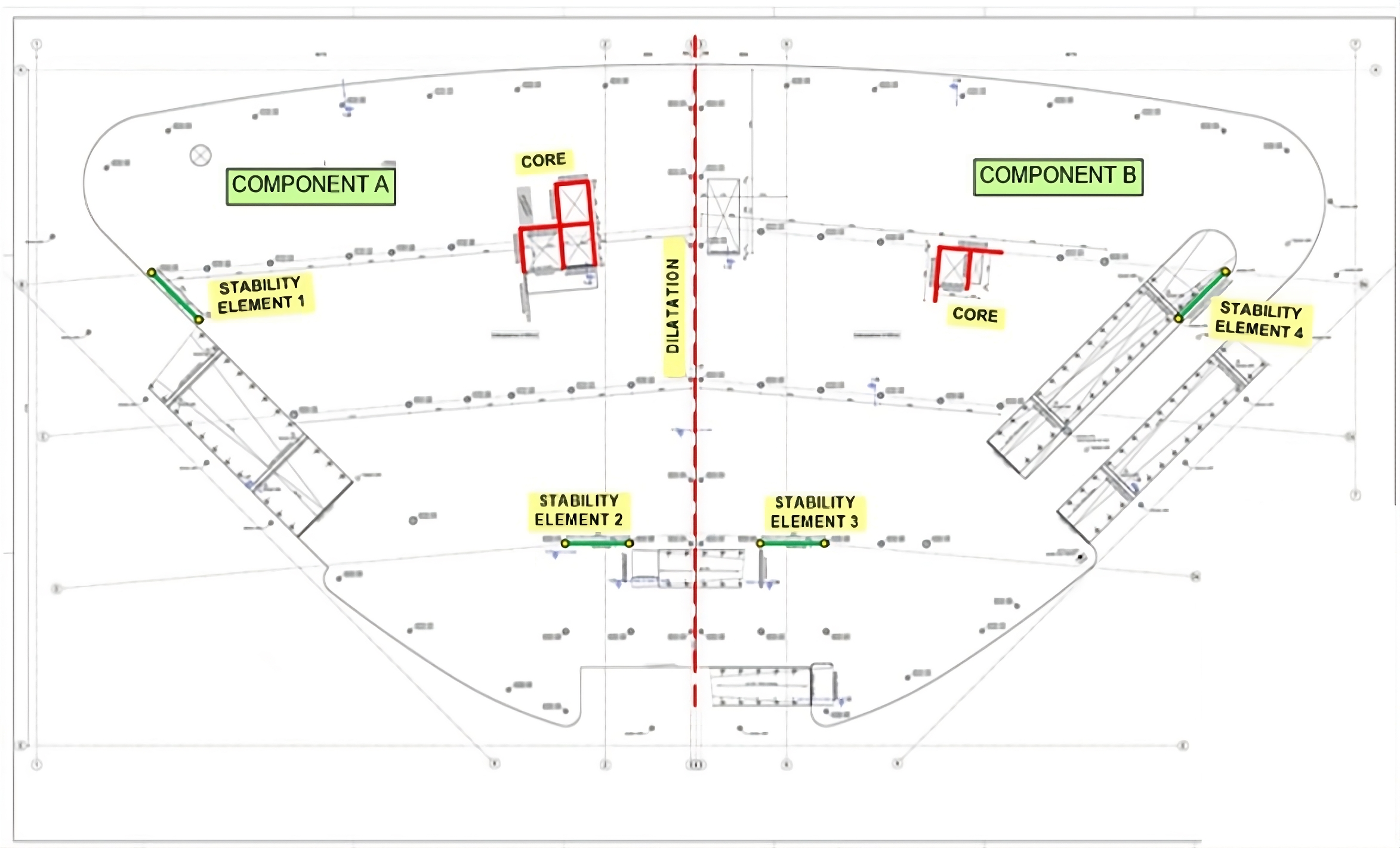
Figure 1: Structural plan
Critical detail
On commission of BAM, the contractor, a research was performed by Adviesbureau Hageman after the cause of the collapse. After studying the available design documents, such as calculations and drawings, it was concluded that in the middle of the span of the floor system a critical detail (Figure 2) was present.

Figure 2: Detail at a seam between two precast planks
The detail is found at the location where the positive bending moments are relatively large, at a seam between two precast plates. In the detail, tension forces in the reinforcement in the plank on one side of the seam should be transferred to the reinforcement in the other precast plank. This is performed by the bond between the reinforcement and the concrete of the plank. Next, the force should be transferred through the interface between the plank and the in situ concrete. From there, by bond, it can be transferred to the coupling reinforcement, which brings the force over to the other side of the seam.
In this detail two critical aspects are present:
• the anchorage of the coupling reinforcement on the plank;
• the capacity of the interface between the precast plank and the in situ concrete.
It is known that in common construction practice the coupling reinforcement is placed directly on the plank. So, the connection between the reinforcement bars and the concrete is not optimal. In addition, the coupling bars, consisting of Ø16-100 at the critical location which, due to the bubbles, should be placed concentrated or bundled at every 400 millimeters (4Ø16-400). This can also have a negative effect on the anchorage length. Especially the influence of the lack of cover on the bars due to the placing on the plank is not well known.
The precast planks are made of self-compacting concrete. From literature it is known that the bond between self-compacting concrete and traditional concrete can be poor. Also, the placing of the lattice girders in the plank, 400 millimeters away from the seam, is so that the contribution of these reinforcement bars, passing the interface, is debatable. Also, it was known that the contractor chose to temporally remove the props below the floor at a time where the compressive strength of the in situ concrete was limited to approximately 18 N/mm² while the supplier of the floor suggested that this should be 34 N/mm². Due to these arguments, it was decided in an early stage of the research to perform experimental research after the moment resistance of the detail.
Experimental research
For this research in the Structures Laboratory Eindhoven, two parts of the floor were reconstructed. The floors had a length of 6 meters and a width of 5 meters, that represented two critical locations of the detail. Here, precast planks were used that were identical to those in the actual structure. An overview of the differences between the two critical locations is given in Table 1 by the codes V and K.
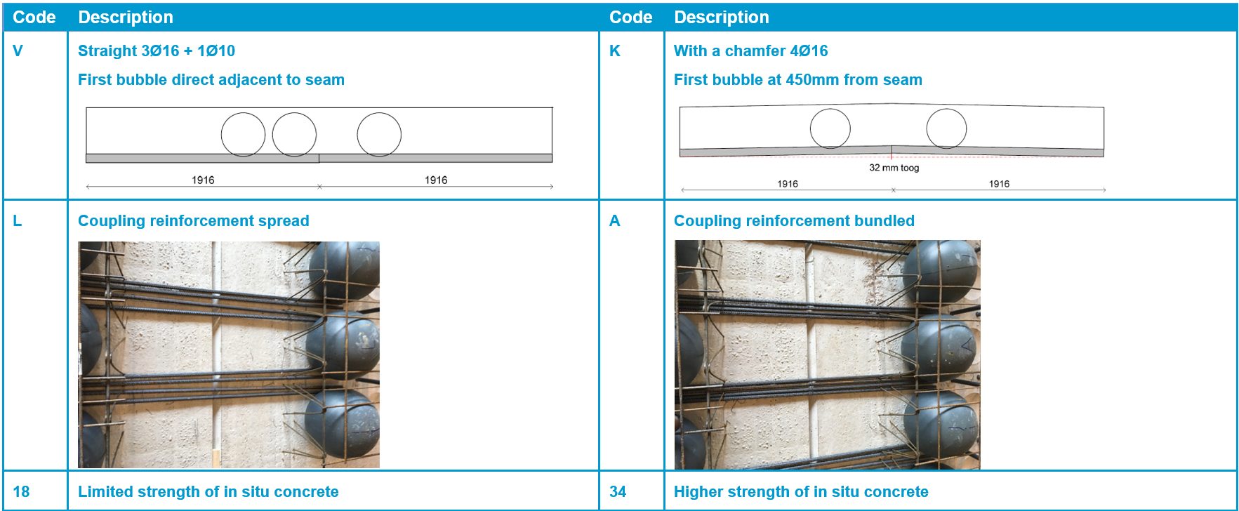
Table 1: Overview of variables tested
In the experimental research, a four-point-bending-test was performed (Figure 3). In the middle of the specimen, a large moment is achieved while the shear force is limited. The specimens, with a width of 0.8 meters, were sawn from the constructed floors. In total, ten specimens were available. Four of these have been tested when the compressive strength of the in situ concrete which was limited to approximately 20 N/mm². The behavior of these four specimens was kind of similar.
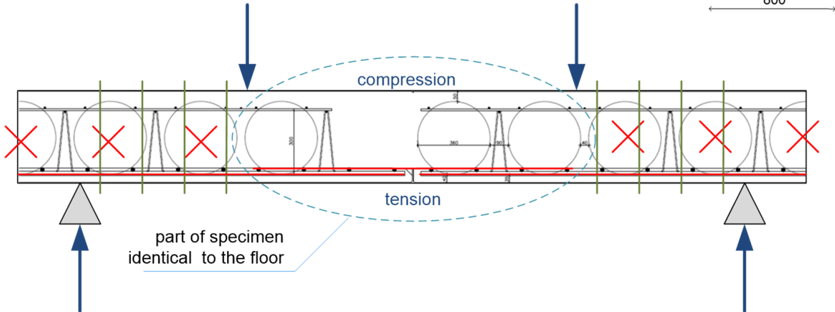
Figure 3: Specimen in the four-point bending test
The load on the specimen could be increased up to 100 kN with a slight increase of deflection. After that, the deflection increased rapidly while the force could be increased marginal. During the test, a crack occurred in the interface between the plank and the in situ concrete. Also, the width of the seam between the two planks increased with an increase of load. The width of the crack at the interface was measured. It could be noted that the crack appeared already with a limited load. At the point where the deflections started to increase rapidly, also the width and the length of the crack at the interface increased rapidly. In the failed specimens, the crack in the interface continued over the length of the coupling reinforcement and after that continued in a vertical direction (Figure 5).
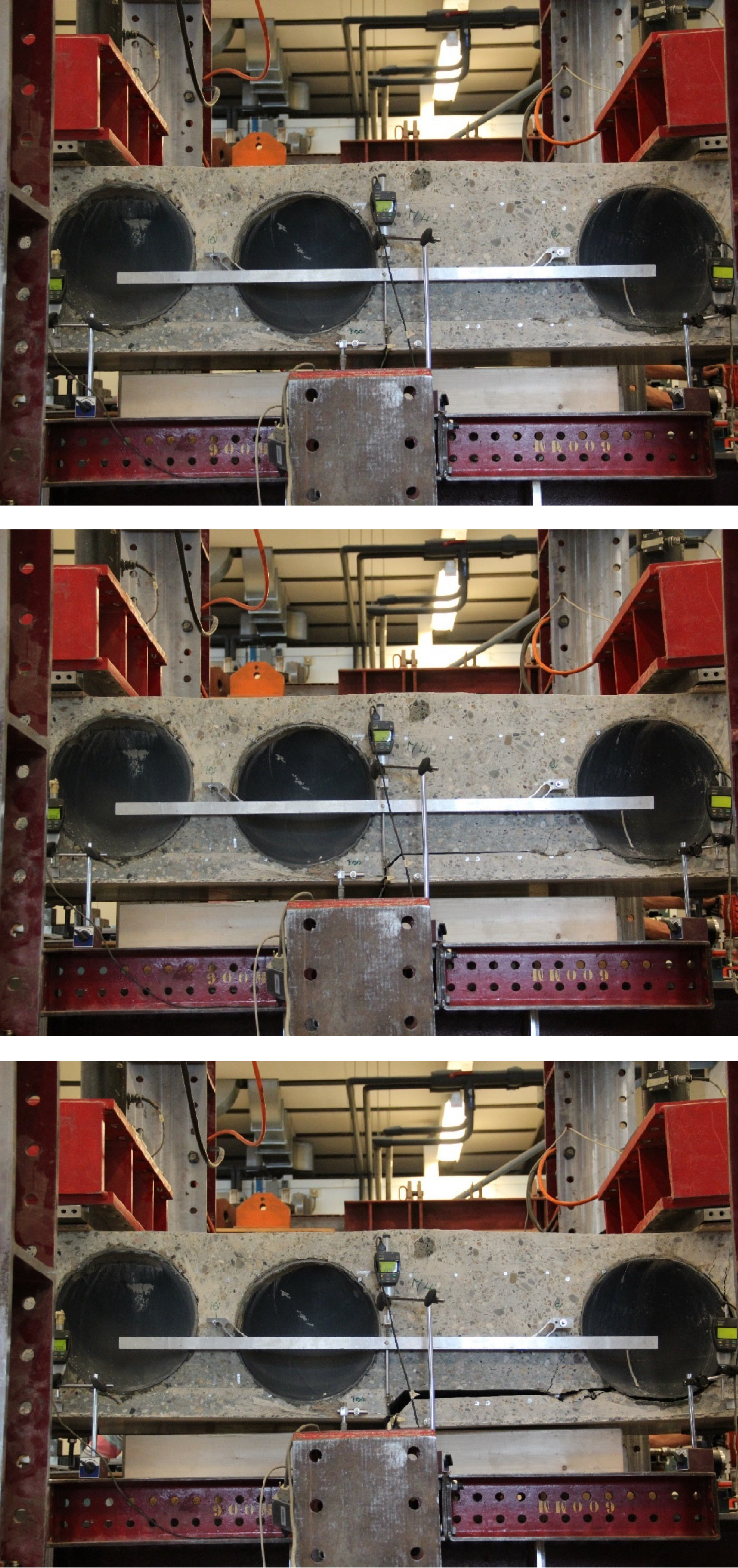
Figure 5: Failure Mechanism of the test specimen
With the limited strength for the in situ concrete in all four specimens, failure occurred due to failure of the interface between the precast plank and the in situ concrete. The way the reinforcement was placed, the amount of coupling reinforcement, the presence of a bubble close to the seam, and a chamfer at the seam, seems not to influence the failure mechanism.
After further increase of the concrete strength, three tests have been performed. These three tests behaved the same as the previous test with the limited concrete strength. The same failure mechanism was found and also the failure load did not vary. Therefore, it is concluded that the compressive strength of the in situ concrete does not influence the failure load. A summary of the test results is given in Table 2.
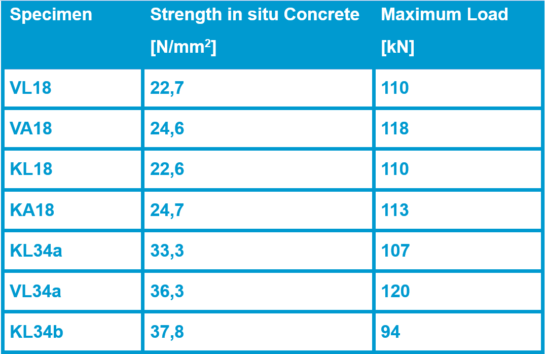
Table 2: Results of four-point bending tests
Cause of the partial collapse
The average moment resistance found from the tests is equal to approximately 128 kNm/m. This is far lower than the moment resistance that was expected. Depending on the amount of reinforcement present this should vary between 325 to 375 kNm/m.
In the area where it is supposed that the partial collapse has started, the moment due to the effect of the permanent load is equal to 120 to 140 kNm/m. It is believed that due to the limited resistance of the detail due to the permanent load in the structure already a redistribution of internal moments was already present. This also could be derived from the fact that prior to the collapse, that particular part of the floor showed large deflections and significant cracks were present on the top of the floor above the middle columns. On the 27th of May, the weather was beautiful and there was a lot of sunshine. Due to this, additional moments and curvatures occurred in the top floor of the structure. At that time, due to the lack of moment resistance and rotation capacity in the detail considered, the floor failed.
Effect of strengthening
After seven tests where performed, the focus of the experimental research shifted to the question whether it
is possible to strengthen the detail. Therefore, the three remaining specimens where strengthened with threated studs. These studs were applied in the anchorage zone of the coupling reinforcement and prestressed and anchored with plates and nuts at the top and the bottom. In other specimens, injectable adhesive anchors were applied from the bottom and anchored in the in situ concrete.
Both strengthening measures were successful. With the strengthening measures it was possible to reach the expected failure load and failure mechanism: being the rupture of the tension reinforcement. A comparison of the load-deflection behavior of some regular specimens and two strengthened specimens is given in Figure 6.
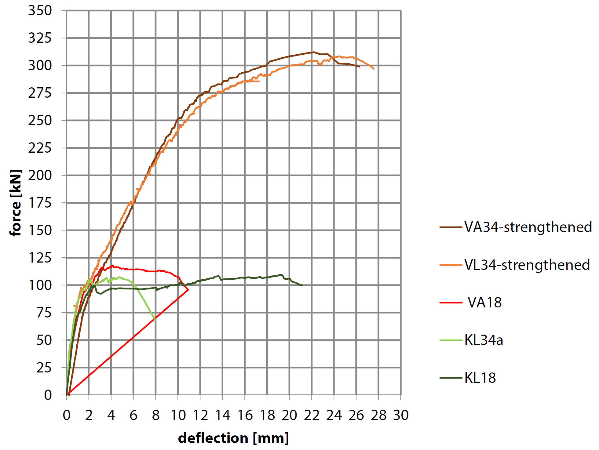
Figure 6: Comparison of the load-deflection behavior of strengthened and regular specimens
Conclusion
The findings of the research after the cause of the partial collapse of the structure of the MPB at Eindhoven Airport are mainly based on the experimental research performed in the Structures Laboratory Eindhoven. I would like to thank my TU/e colleagues from the laboratory for their effort and the nice work that they have performed.
From the research is learned that there is a problem with this particular detail of plank floors and that the structural reliability of several other structures in the Netherlands have to be reassessed. Therefore, the research on the behavior of this detail, used in other configurations of plank floors, will be continued in this new year. The aim of this research is to come up with design rules by which the structural reliability of these kind of structures can be assessed.


