Sightlines and Structures
The inner courtyard of the building housing the provincial government (hereafter referred to as Provincial House) of the province of Gelderland required roofing respecting the cultural and historical heritage of the building. A roof consisting of a tensegrity structure with 29 ETFE (a thermoplastic polymer) cushions, which functions as a climate barrier, transforms the inner court into the logistics center of the building.
In the Provincial House, which was built in 1954, the inner court did not have an important function until this renovation was completed. After the main gate, visitors had to cross the open square to reach the building’s entrance. Now, this same square functions as the main entrance and central point from which visitors and employees make their way through the building. Additionally, the space is now multifunctional, hosting lectures and other gatherings. The area is square, with dimensions of 28 by 28 meters, with a varying rectangular flooring pattern.
The design
The design is based on a previously removed, wide concrete gallery at the roof edge on the 4th floor. This removed gallery is restored, albeit constructed of a different material. A heavy steel horizontal I-beam forms the new roof edge, within which a transparent tensegrity structure is constructed. The 29 transparent ETFE cushions attach to the edge of the fifth floor, which extends several meters behind the edge of the fourth floor. This means the ETFE roof is 36 by 33 meters, larger than the square itself.
The compression members of the tensegrity structure extend, at the upper side, to the level of the ETFE roof. In a grid of 3.85 by 3.85 meters, they support the steel girders onto which the ETFE cushions are connected with aluminum strips. The horizontal pattern of the ETFE girders and cables refers to the flooring pattern, which does not have a regular rectangular pattern. Air ducts are hidden in the roof gutters, and only the innermost cushion reaches the desired pressure using ducts between an adjacent cushion.
The compression members of the tensegrity structure are placed diagonally and are pointed straight to the center of the square at floor level. While walking beneath the roof, the changing perspective and level of transparency creates an ever-changing image. Walking toward the center will result into an increase of transparency; the sightlines align with the axial direction of the compressive elements. This means only the bottom of the compressive elements is visible.
Figure 1: All compressive members are pointed to the center
Figure 2: Concept render
Structural design
A tensegrity structure consists solely of tensile- and compressive elements, where the compressive elements are not connected to one another. The tensegrity structure of this roof consists of a synclastic upper- and lower cable net, pre-tensioned between the steel edge girders and pushed apart by the compression elements. Because the ‘compression ring’ is square, the I-beams are loaded with large axial forces and significant bending moments. This is why an I-shaped girder was chosen.
The structure contains 64 compressive members in a grid of eight by eight. The compression members are connected with hinged connections to the ETFE-girders. These girders transfer most of the load from the roof from the ETFE-cushions to the compression members. Along the edges of the roof, a strip transfers the loading directly to the gutter structure. A downward load will increase the tension in the lower wires and decrease the tension in the upper wires. Upward loading has the exact opposite effect. The required pre-tensioning is the force where no member ever loses its tension completely.
Figure 3: Exploded view of structural members: top: EFTE grid shell, middle: Tensegrity I-beam and cables, bottom: Tensegrity struts
Iterative form finding
The form finding of the cable net is performed using the force density method. The diagonal placement of the compressive members makes this process significantly more complex. The compressive members now influence the horizontal equilibrium in the nodes. Ensuring correct placement and orientation of the compression members, as well as ensuring equilibrium in every node, now requires 32 instead of just two force densities (16 in the upper and lower net). Based on an equally distributed load on the system and a single value for the force densities of all cables, a first cable net geometry is determined where the compression members remain vertical. In this geometry, the nodes are not aligned with the desired vectors for the compression members. An iterative optimization process changes the 32 force density values until the nodes converge to the correct vector. The total margin of error for an ideal geometry is monitored during this process and used as a stop condition for the iterative process. The total force densities of the upper- and lower-net remain constant during the calculation, while the force densities of individual cables are changed after each iteration. These two total force densities determine the upward or downward deflection of the upper- and lower net.
Loading
An equally distributed load as input for the form-finding process does not yield the optimal result with respect to governing deflection and internal cable forces. The height of the building on each of the four sides of the building varies. The building rises seven meters above the ETFE roof on the southern side. This means the load calculations must use an additional asymmetric snow accumulation of up to 2.8 kN/m2 . This asymmetric load is used as input for a new form-finding calculation resulting in an asymmetric cable net with a higher load-bearing capacity and stiffness. However, reducing the symmetry of the roof increases the number of varying force densities from 32 to 144. Despite theoretical structural benefits, a symmetrical cable net was still chosen for ease of construction. However, the asymmetry is accounted for by a higher snow load. This results in higher force densities in both the upper- and lower net.
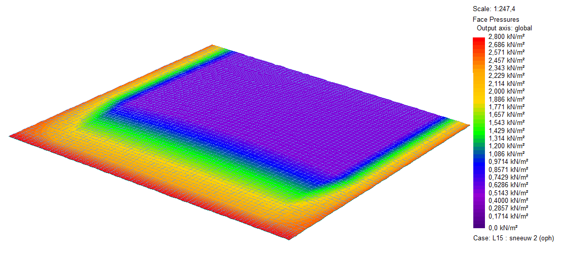
Figure 4: Asymmetry due to snow loading
An extensive study was performed into varying loading patterns and summation of force densities to optimize the geometry and pre-tensioning level of the cable net. Due to the many variables and the iterative calculation process, a parametric model of the cable net was created in Rhino and Grasshopper. The system of linear equilibrium equations in the x, y, and z directions is solved in a Python script. This is all controlled by Hoopsnake, a plug-in within Grasshopper which enables the iterative process. During construction, calculations are repeated with accurate measurements of the node locations along the roof edge.
Detailing
Detailing significantly impacts the structural and aesthetic design of a lightweight structure. Due to the application of high-strength materials, large forces concentrate in a single element, quickly demanding large connections. The connection between cables and compressive elements should be executed without visual impact (no extra thickness). The transfer of forces, therefore, should occur entirely within the compression elements. At every node, two cables cross the compressive bar at differing angles. At the steel construction company, clamping elements are connected to the cables at specific locations. These elements are inserted into a round socket in the compressive element and fitted to an internal laser-cut steel plate, which is covered up afterward.
The connection between the I-girder and the cables must satisfy the same structural and aesthetic requirements, especially at locations where the structure is visible and close by. In the worked-out detail, the force vectors of the cables and the I-girder always cross at one point. The I-girder has vertical and rotational constraints but can independently move in the horizontal direction. This is required to keep the horizontal forces within the tensegrity system and avoid large horizontal forces on the existing building. The cable sockets are hidden within the thickness of the roof edge. The connection point of the cables coincides with a bulge in the roof edge, which creates a slim-looking roof edge.
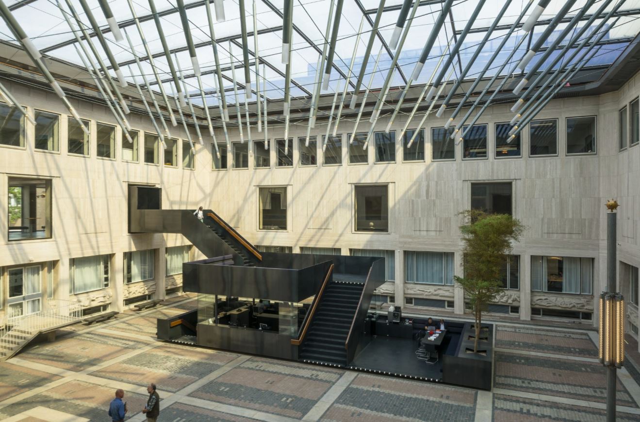
Figure 5: Interior view of the newly created space
Execution
The atrium roof was constructed in the second half of 2016. The I-girders are placed in eight parts and are connected in places where bending moments are minimal. The four corner pieces, where significant bending moments occur, are prefabricated. The ETFE-girders were placed on temporary supports. After that, the cable net with compression elements is assembled at floor level and lifted in its entirety, allowing the compression elements to be connected with the ETFE girder. The cables are subsequently pre-tensioned and connected to the I-girder. Finally, the temporary supports are removed, and the ETFE-cushions are placed.
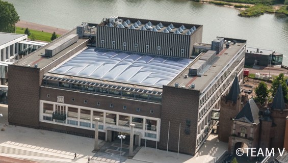
Figure 6: Aerial view of the Provincial House's new roof