SD vs Building physicist
Lightweight houses, buildings for performing arts, buildings close to railways and railway bridges: they are all examples of buildings that ask for special solutions regarding sound and vibration insulation. Especially at low frequencies because the vibrational behavior at these frequencies dominates performance and perception. Controlling low frequency vibrational behavior is the playing field for both structural and acoustic engineers. Where the structural engineer might strive for high stiffness and coupling of structures in favor of structural integrity, the acoustic engineer has a different focus.
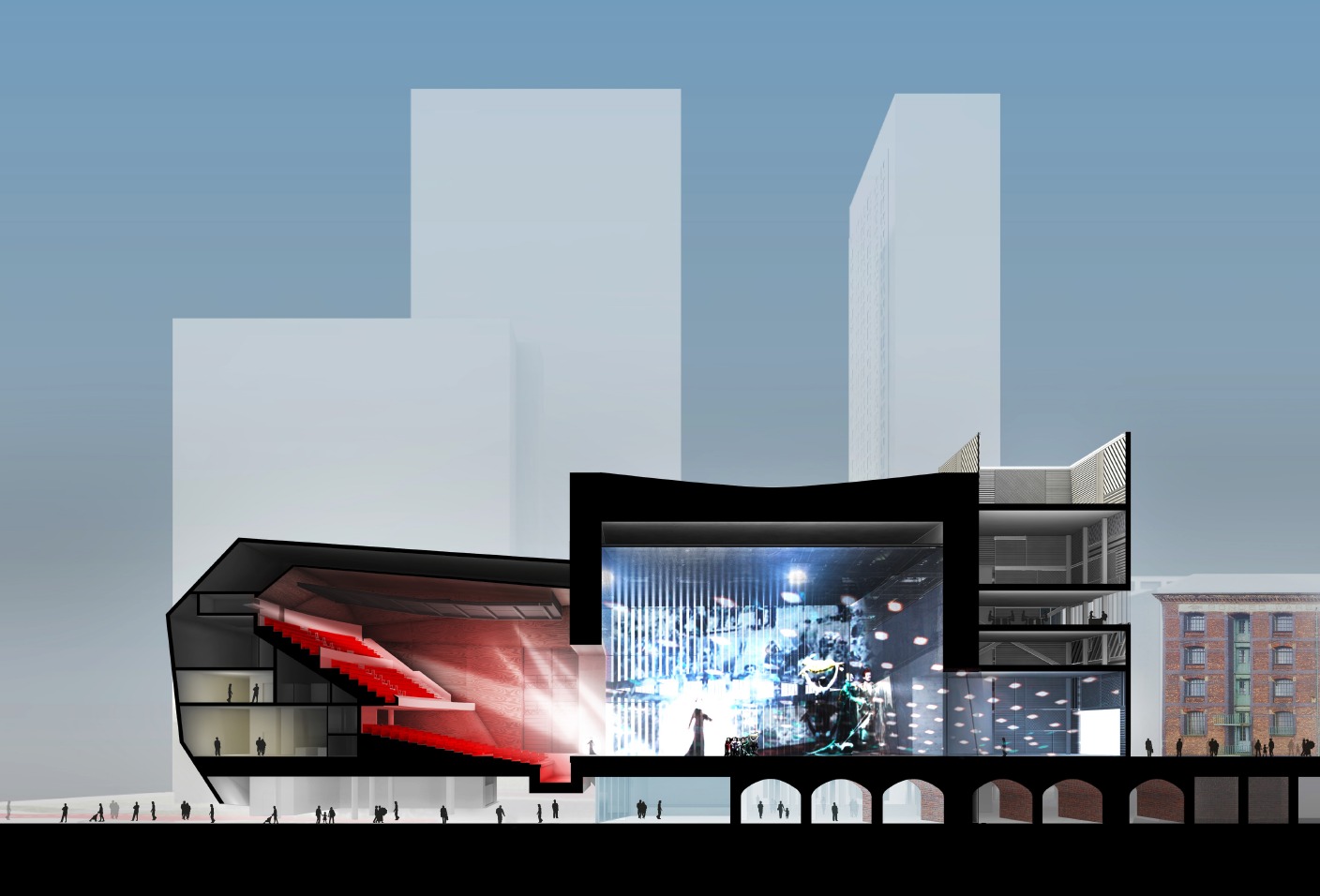
(credits: OMA)
Less stiff and (acoustically) decoupled structures help the building doing what it needs to do: providing sufficient sound insulation. The aspect of isolation of human induced vibration falls in between. A challenging field: not completely unknown; nevertheless, a field where wider dissemination of knowledge and skills help constructing better performing buildings. A field where perfect balance between structural integrity, variable and dynamic structural behavior, human induced and perceived vibrational behavior and low frequency sound insulation is needed. This asks for optimal cooperation between all involved design and construction partners, in particular structural and acoustic engineers. Good solutions from one perspective can be disastrous from other perspectives.
Based on three different project examples, in this article we want to illustrate and explain:
- The background behind sound and vibration insulation requirements.
- Different principle design solutions for different types of buildings.
Sound and vibration transmission paths
The building junction plays a vital role in sound and vibration transmission. The junction is the place where walls and floors meet and where acoustics and vibration get influenced by the structural support of the building. Sound transmission between spaces next to or above each other does not only take place via the direct separating wall or floor. Sound is also transferred via so called flanking sound transmission paths, i.e. paths that bypass the direct separating element but travels via junctions and other structures that are connected with these junctions. This is schematically illustrated in Figure 1 for an airborne sound source (a sound source that directly excites the air) and two spaces next to each other. The contribution of flanking transmission is determined by the building concept, i.e. main supporting structure type, build-up of structures and junctions, and can typically vary between 20% (for concrete buildings) and 80% (for lightweight buildings or buildings with high sound insulation demands) of the total sound transmission. For impact sound sources (that directly excite the structure such as walking) direct sound transmission via the separating floor and flanking sound transmission from this floor via junctions to connected walls and floors dominate the total sound transmission. Transmission from floor to floor (via junctions and other structures) determines tactile vibration transmission (for example floor vibrations due to walking or jumping).
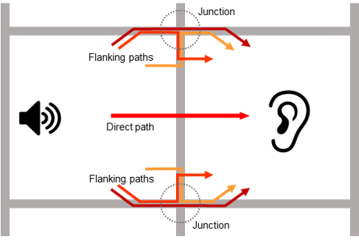
Figure 1: Principle illustration of sound transmission paths between spaces
Sound and vibration insulation
So, we can conclude from the previous section: the contribution of all sound/vibration transmission paths needs to be evaluated in order to be sure that set criteria can be met. Junctions and connected structures need to be designed such that flanking transmission is sufficiently reduced. The sound insulation of the direct sound transmission path between spaces is determined by the sound insulation of the separating wall or floor between the spaces. The sound insulation of a flanking sound transmission path is determined by the vibration reduction in the involved junction and the sound insulation of the elements connected with this junction.
Sufficient sound insulation in regular buildings such as apartment buildings is achieved with:
- Heavyweight stiff elements that are rigidly connected, perhaps with addition of an extra layer such as a floating floor, acoustically decoupled from the base floor;
- Lightweight double or triple non-stiff structures that are acoustically decoupled.
High sound insulation values can be achieved with:
- Multi-layered structures with a heavyweight stiff basis and rigid junctions;
- Multi-layered lightweight structures with acoustically decoupled layers; the lightweight structures are acoustically or even structurally decoupled/separated through acoustic bearings (springs or elastomers) or structural dilatation/separation;
- A combination of 1 and 2.
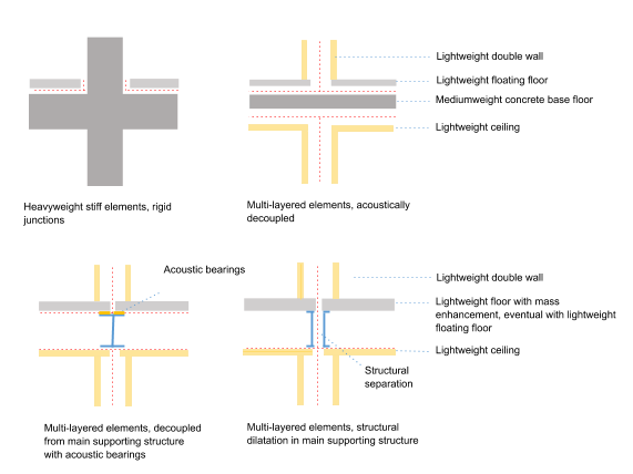
Figure 2: Schematic examples of junctions with location of acoustic bearings’
c.q. acoustic separation or structural dilatation/separation line (in red).
Dilatation/separation lines either are simple gaps or involve spring like
bearings when some horizontal or vertical support is needed.
The low frequency range: the playing field for structural and acoustic engineers Figure 3 illustrates where the playing fields of structural engineers and acoustic engineers meet most: in buildings or building concepts where (high) demands regarding vibrational (tactile* and acoustic) behavior at low frequencies exist. Structural stiffness and rigid coupling of structures and building parts often form the basis of effective design solutions regarding structural integrity. Effective acoustic design solutions often comprise decoupling of structures and building parts, and structures with limited stiffness, in particular in lightweight buildings and buildings with high insulation demands. Acoustic insulation at low frequencies can only be achieved with decoupling working from very low frequencies on (typically from 6-15 Hz on). Due to mass-spring resonance characteristics vibration levels heighten at these very low frequencies. Because this is the part of the frequency range where dynamic structural loading and human induced vibration might also play an important role, apparently conflicting phenomena might occur (and need to be avoided). Optimal cooperation between structural and acoustic engineers is necessary to realize on the edge (optimal) design solutions, direct in line with functionalities strived for and construction concept. From the earliest design stage on, since in that stage the basic structural concept and corresponding junction types is laid out. Sometimes a solution for one aspect inherently also treats other aspects. Most challenging situations occur when a solution for one aspect can have negative impact on other aspects. Then different solutions need to be developed for different phenomena.
* In this context, i.e. sound and vibration insulation, with tactile vibration we mean human induced and perceived vibration, for example vibration due to walking, dancing, and jumping.
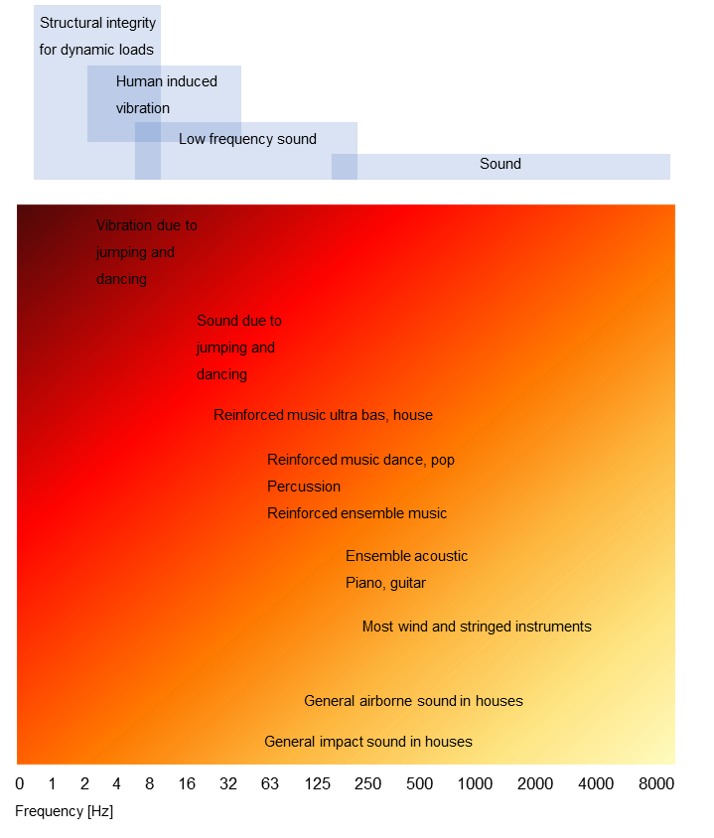
Figure 3: Structural, vibrational, and acoustic aspects, corresponding examples
of vibrational (tactile and acoustic) excitation sources and typical frequency
ranges, and sound and vibration insulation strategies
Case 1: high-rise lightweight apartment buildings
Although not very special in sound insulation demands, high-rise lightweight apartment buildings from wood, CLT (Cross Laminated Timber), steel and other lightweight (main supporting) structures ask for special solutions. At low frequencies the sound insulation of the separating (multi-layered) wall and floor elements tends to be limited compared to concrete walls and floors. This requires thoughtful multi-layered build-ups of the floor and wall elements, and of the building junctions.
In particular, attention needs to go to impact sound at low frequencies, i.e. the octave band 63 Hz (Figure 3). Direct excitation, e.g. by walking, of lightweight floors can cause annoying drumming noise in adjacent apartment. This can be solved addition of an extra mass layer directly on top of the base floor, eventually in combination with a lightweight floating floor or sound insulating ceiling.
Junctions with complete structural separation are a good option for single houses next to each other. However, for high-rise buildings this is not an option. Wind loading for example asks for structural coupling of building parts. This is not necessarily conflicting with acoustic decoupling. Depending on the sound insulation of the building elements connected with the junction, in the junction bearings with a resonance frequency between 10 Hz and 25 Hz generally work, i.e. outside the frequency range where wind loading asks for coupling. Another option is a limited number of structural couplings between apartments. The dimensions of these couplings and connected main supporting structures needs to be such that vibration transmission (for various sound wave types) is limited. Figure 2 shows some junction examples.
Previously the authors have developed calculation methods regarding sound and vibration transmission in high-rise lightweight buildings. The calculation methods and example junction details can be found on the website lichterbouwen.nl. See also the calculation tool SoViST on the website of Bouwen met Staal.
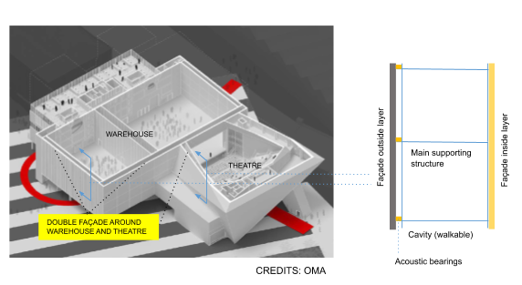
Figure 4: Schematic illustration of facade build-up (credits: OMA)
Cases 2 and 3: buildings with high sound insulation demands
Buildings for performing arts generally have (very) high sound insulation demands, between spaces within the building and between the building and its surroundings. The sound insulation demands are driven by high sound production on the one hand, often at low frequencies, and high sound sensitivity on the other hand. Since these buildings are always unique, and the junctions play a determining role in both the structural (integrity) scheme and acoustic (decoupling) scheme, new junction solutions dedicated to the project are developed.
Case: The Factory (Manchester)
The Factory is going to be home to all sorts of music and artistic productions and performances. Apart from high sound insulation between Factory’s halls (Warehouse and Theatre), Factory’s facades and roofs need to be highly insulating in order to limit noise egress to the (future) surrounding towers. Therefore Factory’s facades and roofs exist of double concrete structures with large walkable cavities in between. The facade/roof leaves are structurally connected via the main steel supporting structure of the building, and at the same time acoustically decoupled by placing the outside facade elements on acoustic bearings thus limiting sound transmission from the inside façade elements via the steel supporting structure to the outside facade elements (Figures 4 and 5).
Case: Tivoli Vredenburg (Utrecht)
After the completion of Tivoli Vredenburg a lack in sound insulation became apparent between the pop concert hall (Ronda) and the chamber music hall (Hertz). Research by Level Acoustics & Vibration showed that four columns connecting both halls were redominantly responsible for the lack in sound insulation; columns of utmost importance in the structural scheme. The columns have been cut through in order to ‘block’ the sound transmission. Spring assemblies have been developed specifically for this project and installed in each column, serving both the structural and acoustic demands. The solution has been proven beforehand with FEM (Finite Element Method) models and SEA (Statistical Energy Analyses) calculations (Figures 5 and 6).
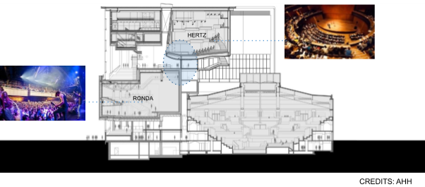
Figure 5: Impression of Tivoli Vredenburg (credits: AHH)
Acoustic performance parameters in bearing design These cases illustrate the potential conflicts in junction design between structural design and acoustics. Often on this topic a first order approach is used in which resonance frequency and static and variable loading are used as the acoustic parameters for the design of the bearings. An example of this is base isolation of concrete buildings exposed to ground-borne vibration.
However, resonance frequency as the basis for bearing design is only valid for simple cases. As soon as the two subsystems that need to be acoustically separated but structurally jointed are of a similar mass and stiffness or when at least one of these subsystems is lacking in dynamic stiffness, the ‘1-degree-of-freedom’ approach is no longer valid and second order calculations are needed to avoid a bearing design with too low sound insulation performance. The three cases in this article are examples of situations where second order calculations are needed.
For a second order calculation we use an ‘insertion loss’ instead of a resonance frequency and a ‘dynamic mass’ instead of static loadings. These are structural dynamic parameters that require numerical or analytical calculations to be determined and checked. From this a bearing stiffness is derived which a bearing supplier can use, together with the static load, to propose a product.
An important message for the structural engineer and for the architect is that ‘second order bearings’ often need more space, typically twice as much as a simple bearing. The Tivoli Vredenburg case is a good illustration of that. Initially the bearing supplier proposed a product, with certain dimensions, based on a first order calculation, disregarding the second order specifications that were supplied. After review the second order specs were used for the design, leading to a bearing that is twice as high (Figure 6).
One can suspect that second order bearings are perhaps needed and sufficient space needs to be reserved, when steel or timber is involved.
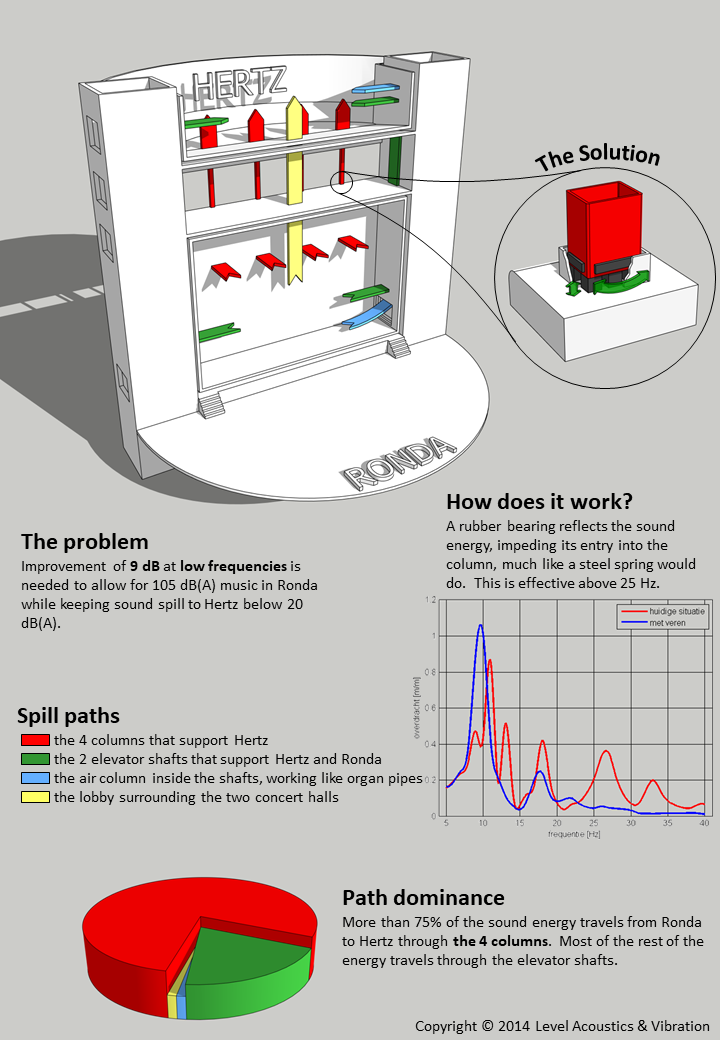
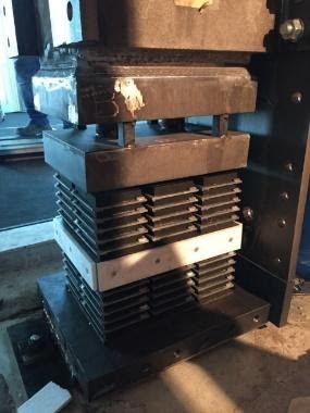
Figure 6: Studies of sound transmission paths and installment of spring
assemblies in columns