Master thesis of Caroline Koks
Adhesive joints that are sandwiched between two substrates are used in the design of various structural applications. To improve the performance of the joint, an understanding of the interaction between the adhesive and the substrate is needed. One important aspect is crack propagation. Cracks can propagate in numerous ways, resulting in different failure mechanisms.
This numerical research focuses on predicting the crack path of an adhesive joint, which depends on geometric, material and fracture properties. A 2D model is built to simulate a Double Cantilever Beam (DCB) test using the Finite Element Method (FEM). The adhesive and the two substrate layers are meshed using quadratic six-node continuum elements. Quadratic six-node interface elements are located in between the continuum elements of the adhesive and the substrate layer. The interface elements are also located in the interface between the adhesive and the substrate, to allow for interfacial failure (Figure 1).
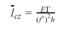
A Cohesive Zone Model (CZM) is implemented in the interface elements to describe fracture. A CZM considers fracture to be a gradual process over a cohesive zone which is restricted by cohesive tractions and allows for crack initiation and propagation. Failure in a CZM depends on the fracture toughness and the cohesive strength. The fracture toughness is the ability of a material to absorb energy before fracture and the cohesive strength can be regarded as the critical stress level before fracture. The cohesive length scale is a measure for the brittleness of a material. E is the Young’s modulus, the fracture toughness, tu the cohesive strength and h the thickness of the adhesive layer.
To mimic a brittle material, the cohesive length scale should have a value around 1.0. However, the behavior will be quasi-brittle since the cohesive strength, in addition to the fracture toughness, plays an important role during failure. A parameter study is performed to study the effects of a mismatch in fracture properties between the adhesive layer and the interface between the substrate and the adhesive layer. As a reference situation, the fracture properties of the adhesive and the interface are equal. For this situation, interfacial failure is observed, i.e. delamination occurs between the adhesive and the substrate layer. A mismatch is obtained by varying one of the values of the fracture toughness and the cohesive strength of the interface. Several failure mechanisms in addition to interfacial failure are observed: serrated interfacial failure, crack deflection, alternating crack deflection and in-layer failure, Figure 2. The transitions between the failure mechanisms are plotted in black in a failure map as a function of the mismatch in cohesive strength and fracture toughness, Figure 3.
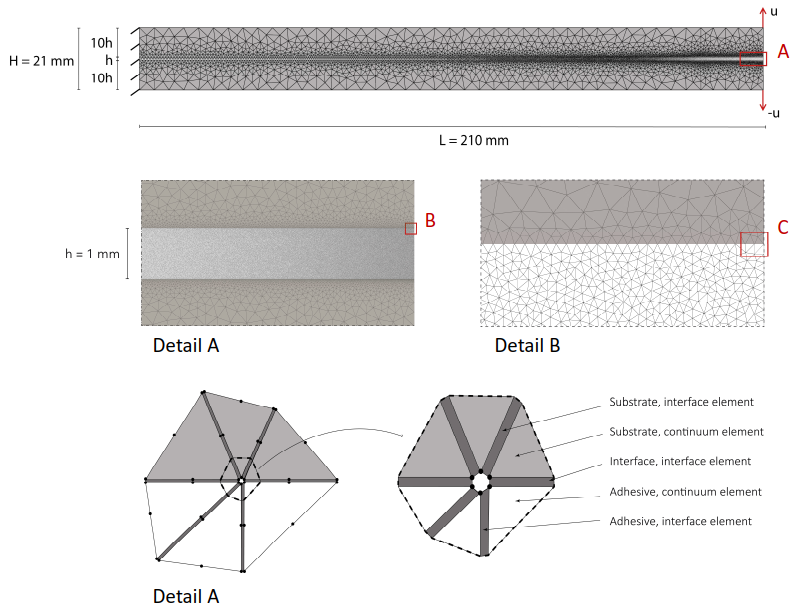
Figure 1: Numerical model of the Double Cantilever Beam test

Figure 2: Observed failure mechanisms
The parameter study is repeated for a reference set with an increase in the stiffness of the substrate layer, and by an increase in the cohesive length scale by decreasing the ultimate strength of the adhesive and the interface. It was found that an increase of the stiffness of the substrate does not have an influence on the trend of the failure map as presented in Figure 3. However, increasing the cohesive length scale, i.e. increasing the ductility of the material, does have an influence on the trend of the failure map and shows that the transitions between the failure mechanism that are plotted in red, are mainly influenced by the mismatch in cohesive strength.
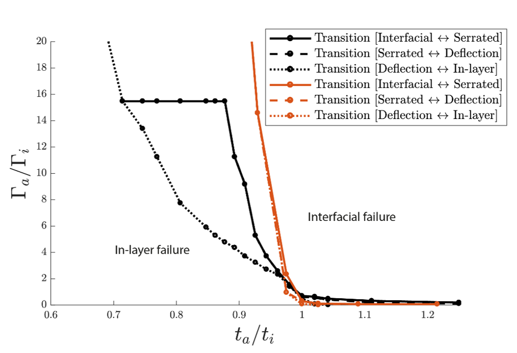
Figure 3: Failure map of the transitions between the failure mechanisms
It is found that an alternating crack path trajectory can occur when the interfacial strength is lower than the adhesive strength and when the interfacial toughness is considerably high compared to the fracture toughness of the adhesive layer. The dimensionless load-deflection curves in Figure 4 shows that an alternating crack path results in a higher failure load and in a higher toughness path compared to the other observed failure mechanisms. The load jumps in the graphs indicate the moment of crack kinking. To obtain the desired behavior of an adhesive joint, the mismatch in fracture properties should be considered in the design process.
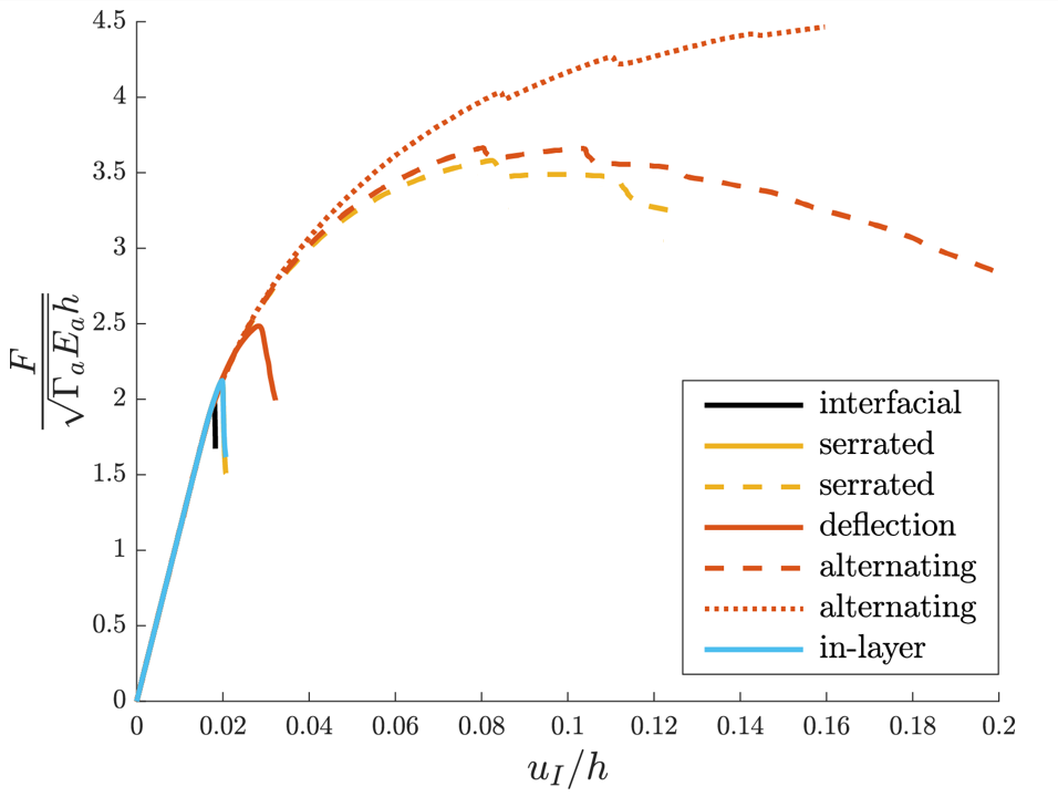
Figure 4: Dimensionless load deflection diagram