Master Thesis of Olaf Vens
Concrete is one of the most used materials in the world. It is a very versatile material that allows for structurally simple structures, like a classic beams and columns building. On the other hand, it also allows for architectural pieces, for example the Portuguese National pavilion by Siza or the shell structures from Isler. However, all these structures have the downside that formwork is needed for it to be cast.
Especially architectural structures need formworks that are not reusable, with unique and multi curved shapes. This results in a large amount of waste materials. Constructing buildings with a concrete 3D printer allows for a large degree of form freedom without the need for wasteful and labor-intensive formworks. Besides a lack of formwork needed, a 3D printer also allows for structurally efficient printing. It is possible to place the printed materials there where they are needed. At the moment, one type of optimization is largely used and researched: efficient design through geometry. Efficiently curving planes result in strong elements, as a curved section is more stable and can withstand larger forces before buckling out of plane. Using this optimization as a starting place, there are still large steps that can be taken to optimize concrete printing. Mostly by locally using other types of concrete or by using other sections.

Figure 1 A/F: f.l.t.r.t.b wall as printed now, single load-carrying wall, braced wall with pins, braced wall with printed snake, insulated wall with warm concrete, effective printed strong concrete
What to analyze
In this study different wall compositions will be analyzed and compared to see what holds of the initials preconceptions about 3D printed concrete. Because it can pretend to be durable, but if you need too much material to make it sustainable, can you still call it as such. To study this, different wall compositions are being analyzed. These types can be seen in Figure 1. The first option is a wall printed as is done now. This is to set a benchmark and see whether this might be the best option after all. The second option is printing one leaf with the required thickness to be a load-carrying wall. The idea is that this would require more concrete to obtain the same loadcarrying capacity as using both leaves as load-bearing. In order for both leaves to be load-bearing, they need to be connected by foam, bracing, or warm concrete, because it does not have any buckling supports. However, the advantage of this composition is that you only have one type of concrete which can be completely reused or recycled. The third and fourth options both contain bracing. The braces of the third option are pins made from a different material, resulting in smaller thermal bridges. However, this does introduce another material that would have to be separated in a potential end-of-life situation. In the fourth option the brace is a concrete printed snake. Both compositions have the advantage that they support the load-carrying wall for buckling, potentially improving the load-carrying capacity. The last two wall types again are very similar. Both are largely composed of warm concrete, a material not particularly good for load-carrying. However, since all the material is still concrete, the material kan be fully recycled in an end-of-life situation. In all other situations the material largely behave the same as the original wall type.
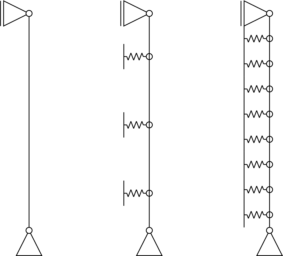
Figure 2 a/c: Structural simplification of wall compositions
How to analyze the different wall types
The main analysis performed on the wall is a buckling check. The way this is calculated differs per composition, but in all cases the results stem from the Euler buckling formula.
 (Equation 1)
Using Potential Energy, we can derive the base formula for the standard buckling situation and when it is supported by a finite amount of springs as seen in Figure 2 a and b. The formula for an infinite amount of springs, as in Figure 2 c is derived by Friedrich Engesser and results in a formula not dependent on the buckling length.
 (Equation 2)
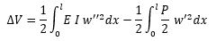
Continuing with the derivation of the first two simplifications. We start with the normal expression of Potential Energy, with w being the deflection and P the applied load and N0 = -P.
 (Equation 3)
This needs to be extended to include the influence of the springs in the total potential energy. This is done by adding an additional term to the formula which is a sum of all spring stiffnesses multiplied by the deflection at the location of the spring cubed.
 (Equation 4)
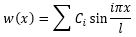
In this extension k stands for the spring stiffness, s for the number of springs, and i is the index of the summation. The next step is to determine the shape function. As in its essence, it still is a system pin supported on both ends a sine function is most probable to be a correct approximation of the shape. This assumption is also supported by Alfutov in the book Stability of Elastic Structures. Therefore, with an unspecified amount of terms, the shape function results in Equation 5.
 (Equation 5)
C is a constant and i is the index for the number of terms used in the shape function. Using these formulas, it can be determined at what stiffness the springs can be considered as intermediate pin supports. For the first four situations, the derived functions can be seen in Table 1. For more springs, the by now visible pattern can be continued. For each row, there are also buckling forces beyond the point it reaches the classic Euler formula. However, it is chosen to only show the critical forces until this point for easier reading and it is assumed to be known for these cases. From this table, it can be read that for all amount of intermediate spring supports the Euler buckling formula also appears preceded by a factor depended on the spring stiffness.
Implementation of the analysis
The derived formulas then are implemented in a grasshopper model, with which can be checked whether the maximum buckling forces are exceeded. In the grasshopper model the maximum load on the structure is calculated using a plugin that allows the integration of SCIA Engineer to calculate the load on the load-carrying wall. In the grasshopper model the different wall types are all implemented and can thus be systematically checked for which setup the best load carrying capacity is given. With this information, different optimizations can be done. On the one hand it can be optimized just for load-carrying capacity and the least amount of concrete used. On the other hand, a possibility is to implement a small addition to the script and to optimize for something like the environmental impact of the complete lifecycle. In the end, the script can be used to generate a lot of different designs and quickly check whether they hold in terms of buckling and maximum stresses.
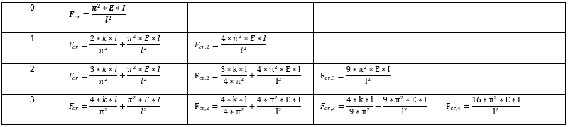
Table 1: Buckling forces with different amount of springs