Master Thesis of Pieter van Loon
In the Netherlands, the Architecture Construction and Engineering (ACE) industry is responsible for close to 25 percent of national waste output. On top of that, the economy of the Netherlands needs to be 100 percent circular by 2050. All the while, Dutch regulations assume timber to be incinerated at the end of its first life cycle. However, when timber is viewed from a circular economy perspective, the sequestered carbon will be stored for significant periods of time, greatly reducing the environmental impact of timber as a structural material.
Furthermore, the efficiency of the ACE industry has been very stagnant since the second half of the previous century. On average, non-farm industries (textile, electronics, automotive etcetera) have seen a productivity increase of over 50 percent while the ACE industry saw no increase. Recent developments in robotic manufacturing aim to close this gap while catering to the highly custom and high-stakes demand of the ACE industry. Robotic fabrication is not only good for automation and faster construction times, but it also opens the door to mass customization and light-weight construction.
The goal of this thesis is to provide a solution to the affairs mentioned above, by means of a tool that can generate a timber roof truss from reused elements. The truss geometry is generated in a two-step optimization process. The first step, a Discrete Truss Topology optimization (DTTopt) solver from Phoenix3D [1], searches for an optimal truss topology within the boundary conditions. The second step, a Best-Fit solver, aims to optimize the stock use in the found topology. The evolution of the two-step optimization is illustrated in Figure 1.
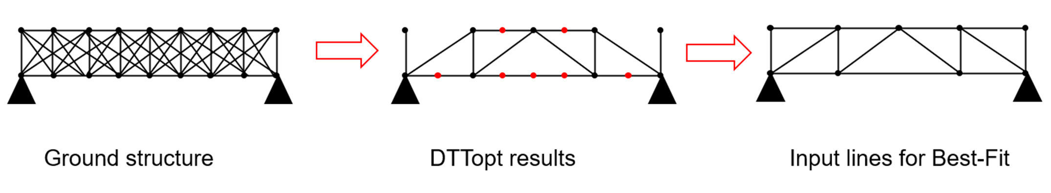
Figure 1 : Evolution of ground structure during two-step optimisation. Left: ground structure before DTTopt. Middle: Ground structure resulting from DTTopt. Right: Ground structure for Best-Fit solver
The most important boundary conditions of the DTTopt solver are the ground structure and available section sizes in stock. As figure one shows, the ground structure is a simple collection of points connected by straight lines. The solver works out which lines contribute to the overall performance, which it assigns a section. The lines which do not contribute much to the performance get removed. In contrast to more conventional topology optimization solvers, the DTTopt solver can only assign discrete values to the ground structure. So, if a line only contributes a little to the overall performance, it can either get a section from the stock or nothing, no value in between. This discreet optimization means that the ground structure is specifically optimized for the available section sizes, but it also results in way longer computational times.
Because the DTTopt solver is computationally hard to solve, the stock constraints are relaxed. It only considers section areas, not quantities or lengths. The quantities and lengths are taken into account by the Best-Fit solver. The result of the DTTopt is the ground structure for the Best-Fit solver, so the Best-Fit solver is simply an element assignment problem rather than a topology optimization problem. The user can choose whether the objective of the Best-Fit solver should be minimal structural mass or minimal cut-off waste. In the first case, the solver simply assigns elements such that the truss is as light as it can be with the given stock (while still having a unity check smaller than 1). When the minimal cut-off waste objective is chosen, the solver determines which stock elements should be used so that a minimal amount of cut-off waste is generated (while still having a unity check <1). Figure 2 illustrates how the different objectives can lead to different use of the stock.
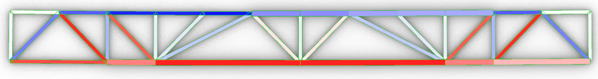
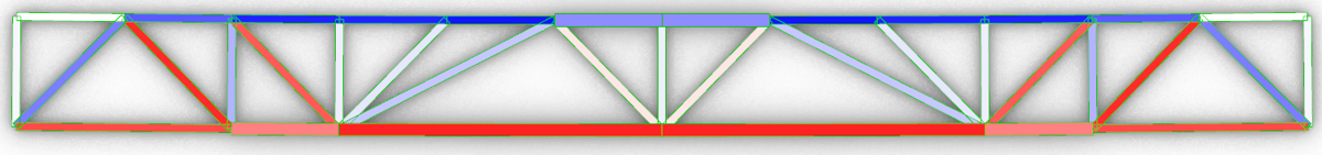
Figure 2 : Different results from Bes-Fit solver. Top: objective is minimal cut-off waste. Bottom: objective is minimal structural mass.
The truss members consist of double timber elements. At the nodes, multiplex plates are present in between the members to facilitate the connections. The multiplex acts as an isotropic connector plate, allowing for efficient and predictable screw patterns to connect the members. The largest screw diameter that is still governed by ductile failure, see Figure 3, is calculated for each element. With the ideal screw diameters known, the required number of fasteners for the shortest connector plate is determined in the following steps:
1. Determine thickness connector plate
2. Check maximum feasible screw diameter
3. Check possible number of screws perpendicular to the grain
4. Check required capacity
5. Determine most efficient spacing parallel to the grain to reach required capacity.
These steps are automatically run for all connections, resulting in details like the one in Figure 4.
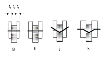
Figure 3 : Failure mechanisms of timber-to-timber screwed connections (k is preferred)
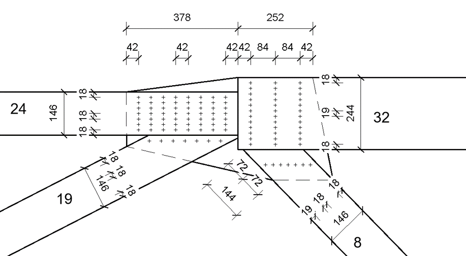
Figure 4 : Example detail from tool
The double members furthermore facilitate a very simple stacking process. A single robot arm fitted with grippers and an automated screwing machine is able to fabricate any resultfrom the tool, as long as it consists of two or less identical element thicknesses. Figure 5 illustrates the fabrication process. Five databases of reused timber, based on practice, have been constructed for this thesis. Out of these five, two consists of elements with only two distinct thicknesses, and a
third consists out of three distinct thicknesses.
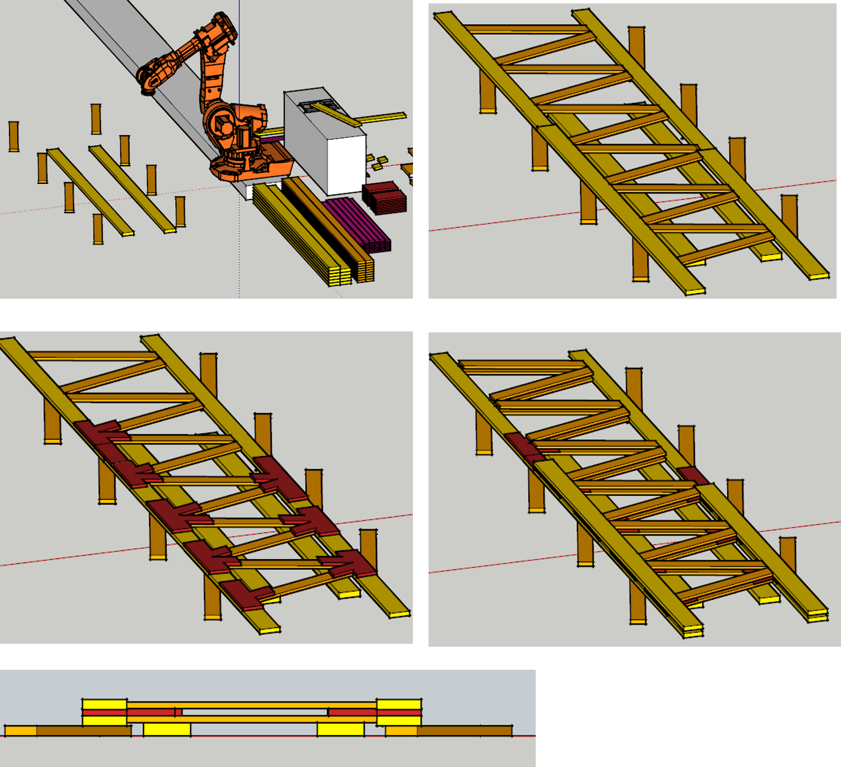
Figure 5 : production process of truss. 1) lay down temporary formwork from waste 2) place first layer of truss 3) place connector plates 4) place second layer of truss and screw connections
To test the tool, seven case studies have been conducted. All case studies are subjected to load case combinations of self-weight with variable (roof) load or simplified wind loads. The base case spans 14 meters, with a structural height of 1.2 meters. Figure 6 shows the truss results from the base case. In other cases, the influence of different parameters is explored, both for physical dimensions as different databases. The base case is elaborated the most, including detail drawings (like Figure 4). All cases yielded feasible truss designs generated from a stock of discarded timber.
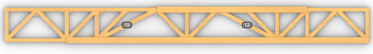
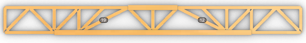
Figure 6 : Results case 1. Top (min waste) – structure = 300 kg, waste = 30 kg
Bottom (min mass) – structure = 268, waste = 33 kg
From the case studies, some interesting conclusions can be drawn. It is very case-dependent whether or not it is worthwhile to base the second optimization on minimal waste or minimal structural mass. For some cases, the difference in cut-off waste was negligible between the two optimization criteria. Secondly, the sizes of the stock sections greatly influence the spannable distance of the truss and the efficiency of the truss. Thirdly, in the best case, a theoretical optimal structure (disregarding stock and robotic fabrication) is just 33 percent lighter than the tool output. Finally, buckling of truss members is no issue in most cases. However, for some cases it needs further investigation.
References:
[1] J. Warmuth, J. Brütting, and C. Fivet, “Computational tool for stock-constrained design of structures,” in Proceedings of the IASS Annual Symposium 2020/21 and the 7th International Conference on Spatial Structures, 2021, no. CONF, pp. 1–9.