Covered by a Cloverleaf
The building EDGE Amsterdam West is part of the final phase of a 48,000-square-meter redevelopment. At the request of EDGE Technologies, Architekten Cie refitted the building to a high-quality, sustainable office environment. The new atrium roof plays an important role regarding sustainability aspects and the overall performance and perception of the building.
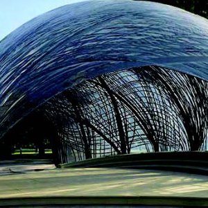
This circular building is located on the Basisweg 10 in Amsterdam. A roof was desirable in order to transform the central outdoor space, with a diameter of 76 meters, into the new heart of the building. The glass dome allows daylight to penetrate deep into the atrium, creating high-quality workspaces and significantly reduces energy consumption.
Design phase
During the first conversation between Branimir Medic (Architecten Cie) and Arjan Habraken (SIDstudio), no final design concept was decided upon, but simply a vision regarding lighting, transparency, energy generation, and sustainability. Subsequently, many design variants have been studied, including origami structures, a timber structure with ETFE cushions, and the sunflower-like structure shown in Figure 1.
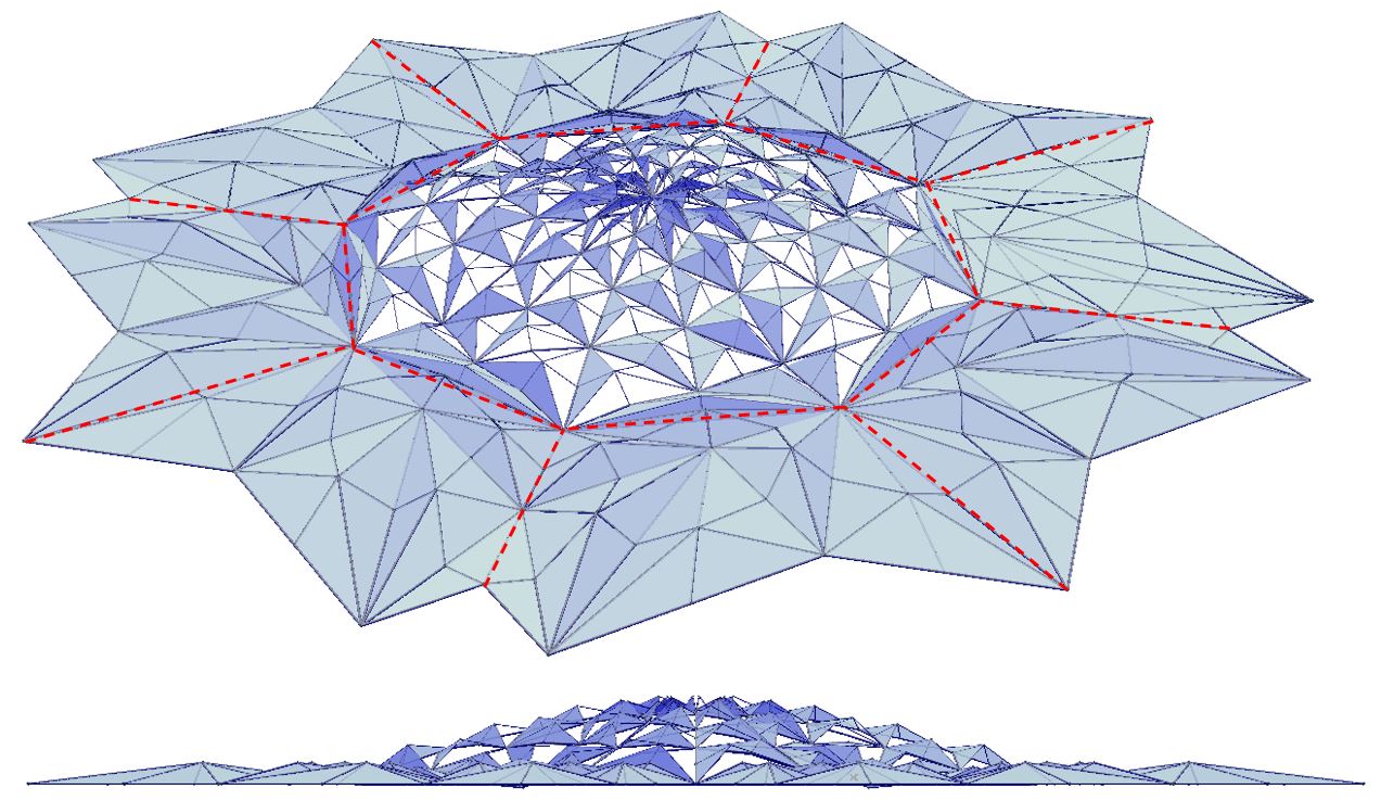
Figure 1: Sunflower shape design concept
The pattern in this figure, however, exhibits no clear relation with the existing building. Construction drawings and internal communication predominantly work with an orthogonal grid. However, an octagonal tessellated pattern could cover the building and atrium floorplan without discontinuities, see Figure 2. This pattern was the right way to go.
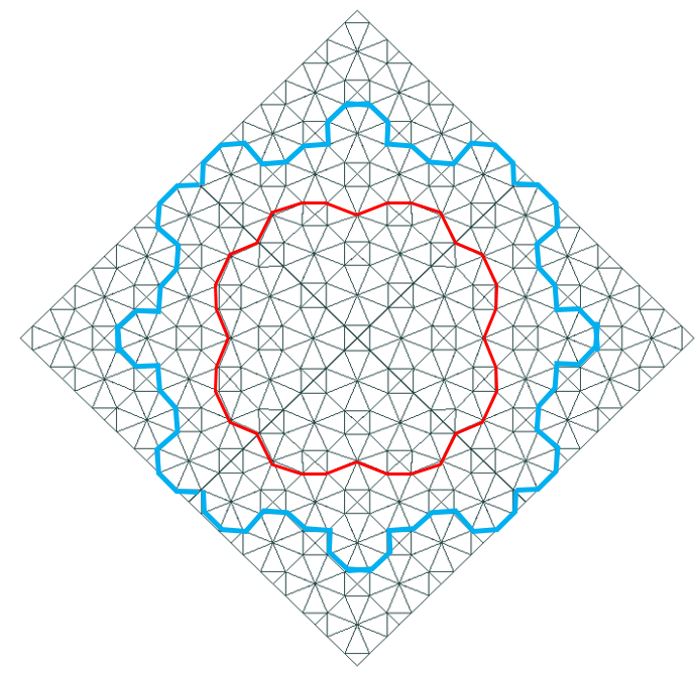
Figure 2: Tessellated pattern with the edge of the existing building (blue), and the edge of the new dome (red)
Using this octagonal pattern to construct the dome creates a structure, of which the edges make a four-leaf clover, seamlessly connecting to the existing vertical load-bearing structure. Every triangle within this pattern features a long side of 9.4 meters and a short side of approximately 6.5 meters. These dimensions are too large for a glass panel. Therefore, a secondary structure is designed, as shown in Figure 3.
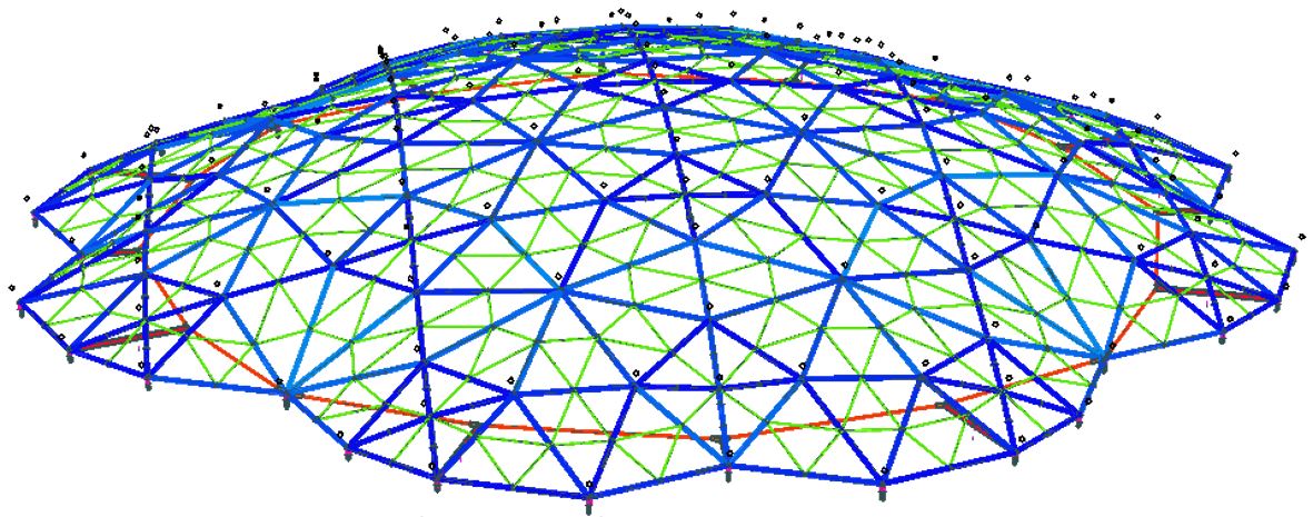
Figure 3: Load bearing some structure; primary structure (blue), secondary structure (green), and tensile ring (red)
Structural principles
The dome structure predominantly transfers its self-weight, glass, wind, snow, and temperature loading by axial forces. In the vertical direction, the roof is supported at 32 points , located at the connection nodes of the edge elements. The horizontal forces created by the dome are resisted using a tension ring, see Figure 3. The existing building cannot resist these horizontal forces due to pre-existing dilations. This tensile ring is located in the same horizontal plane as the dome supports. It is connected not only using connection beams at twelve locations, but also directly to nodes of the dome structure at four places . The tensile ring is tensioned by adjusting the twelve radial connection beams. This pre-tensioning is performed before the placement of the glass panels, which means the dome does not reach its final shape just after tensioning.
The roof is stabilized using horizontal connections to the concrete roof plates, which are connected to the existing concrete stability cores. Ensuring the roof can expand in all directions during temperature fluctuations, without translation or rotation, is crucial. The 32 supports are executed as pendulum columns. Both ends of the columns are hinged to allow movement. Two columns support the dome in the x-direction, and two in the y-direction, see Figure 4.
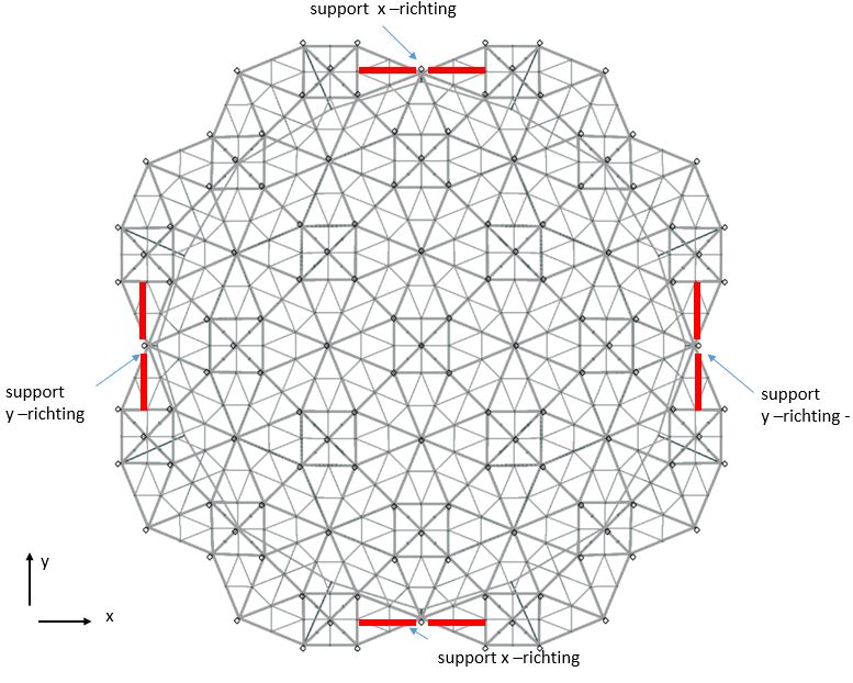
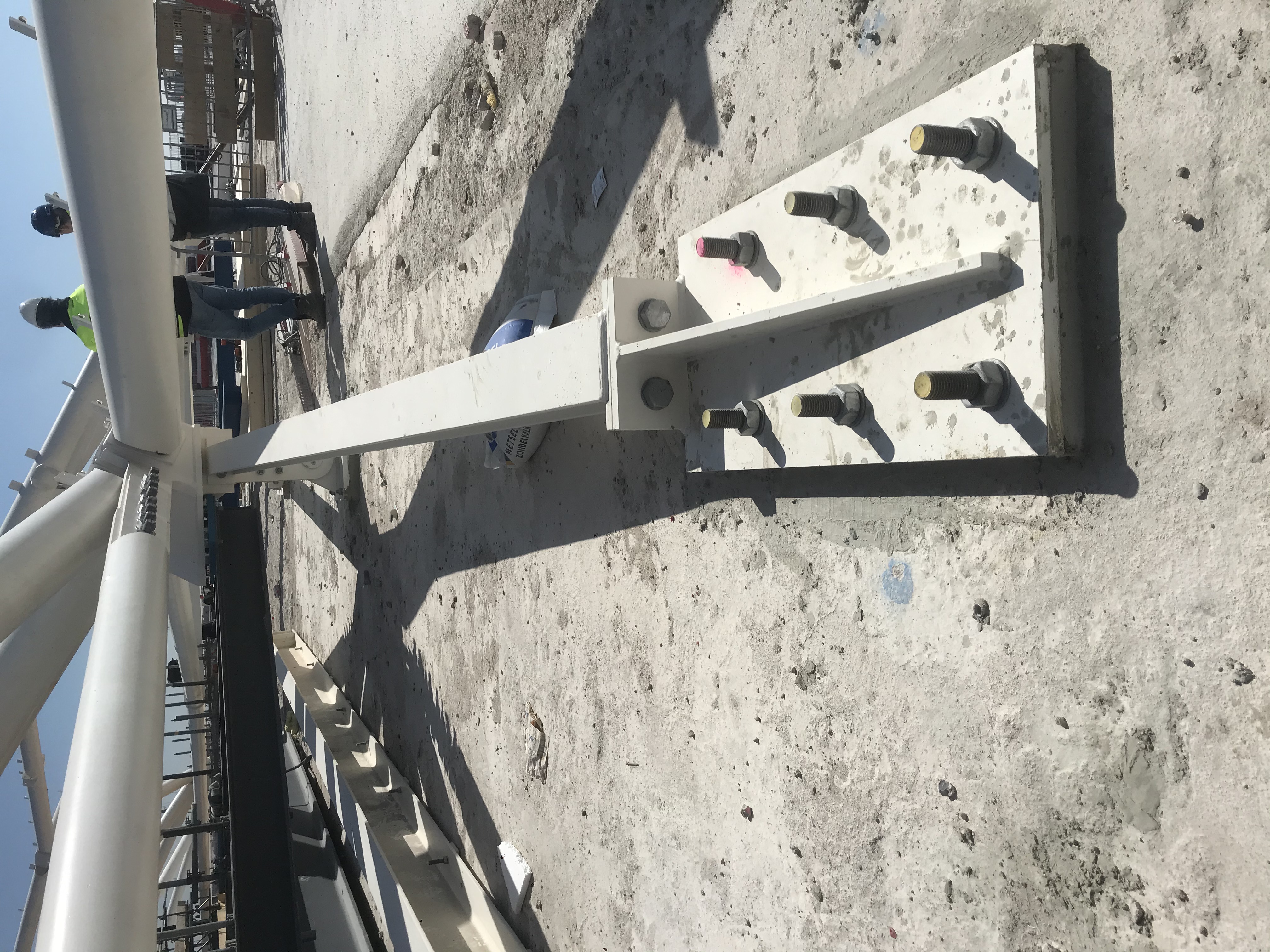
Figure 4: Support locations (left) and picture of supports (right)
Structural verification
The starting points for determining the right dome geometry are the octagonal grid, the outer edge in the shape of a four-leaf clover, and a maximum allowable height. Multiple form-finding methods have been considered, including the force density and particle spring methods. The internal forces affected by the geometry are adapted during the form -finding using an iterative process.
As the dome edge is cloverleaf shaped, additional curvature is created, adding stiffness to the structure. The final geometry features two mirrored symmetrical sections, which both occur four times. This symmetry not only reduces the required engineering but also provides a metric to verify calculation results.
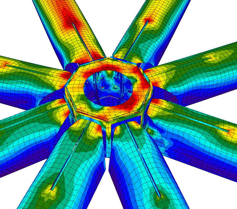
Figure 5: Finite Element Method analysis of a node
Details are analyzed using FEM models to verify strength and stiffness, see Figure 5. Because an endplate connection with an axial tensile force has less rotational stiffness compared to the same connection with an axial compressive force, stiffness will vary. Therefore, the average maximum and minimum stiffness is determined for all endplate connections, and the dome is verified for both these variants. Similarly, the level of pre-tensioning of the tensile ring is practically impossible to predict exactly. The main calculation is performed using a minimum level of pre-tensioning and a level twice as high. The 36 load cases, result in 680 load combinations.
Other calculations are performed after the design is verified using linear elastic analyses. These include non-linear, local buckling, global buckling, eccentricity, support settlement, calamity, and mid-construction calculations. The final two calculations are briefly elaborated on below.
Calamity calculations
To evaluate the robustness of the dome , three failure scenarios are considered; failure of a main grid member, support failure, and failure of the tensile ring. Due to the triangular grid of the dome, a secondary load path exists in the first two cases without worrisome extra stresses. However, failure of the tensile ring cannot be compensated by a secondary ring. Or could it? The edge of the dome structure can compensate, but only partially. Therefore, the tensile ring is connected directly to the dome at four places. If the tensile ring fails, only one-fourth of the ring loses its structural function. In this situation, extreme deformation and plastic hinges do occur, but progressive collapse is prevented, see Figure 6.
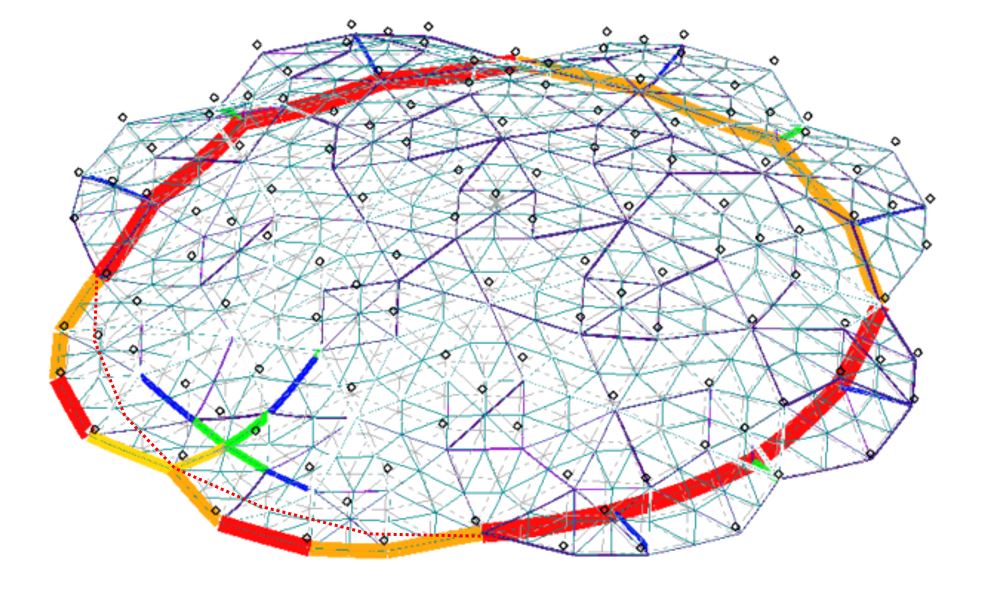
Figure 6: Results of failure in the tensile ring
Detail design
Due to the differences in loading, edge thickness, and angles, no two connection nodes in a one-eighth part of the structure are identical. It is important to find regularity and repetition not only for aesthetic purposes but also for the production and installation of the steel structure. A ‘washing drum’ connection node principle was chosen, where the connection node is the fixed and repeating element. Steel members are connected to this element with an endplate connection with differing angles. This method is beneficial because the steel tubes can be cut using machines, allowing for much tighter tolerances and minimal defects.
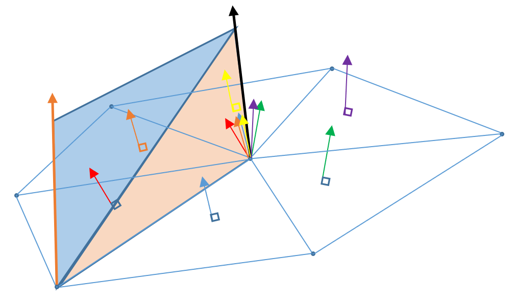
Figure 7: Node orientation is the average of the normal vectors of surrounding planes, node orientations are therefore different at each end of the vector
Every node element has a unique orientation. The central axis is the average of the normal vectors of all adjacent triangular planes. Both sides of a member may therefore have a different node orientation. The members of the calculation model are split in two such that each part has a unique value for the orientation of the node to which it connects, see Figure 7. This is relevant for the node detail calculation; the nodal forces must have the correct orientation.
The calculations performed by SIDstudio resulted in thousands of internal forces. Manual checking is, therefore, not a viable option. Possibly decisive nodal forces must be found for the differing nodes. SIDstudio and Oostingh (steel contractor) agreed on a comprehensive data exchange approach. By using smart programming, various tables are coupled and decisive loading combinations are determined for every individual member, as well for the interaction between members and nodes.
Construction
For safe and rapid construction, a construction sequence has been worked out. Each step has been verified and carefully inspected to determine whether temporary forces and displacements significantly impact the final structure. During steps one to three, a steel ring structure is constructed, including the tensile ring, before realizing the dome in a course grid. The steel structure rests on 25 temporary supports during construction to maintain the appropriate shape. Temporary scaffolding was constructed for the dome and to accommodate the renovations beneath the dome.
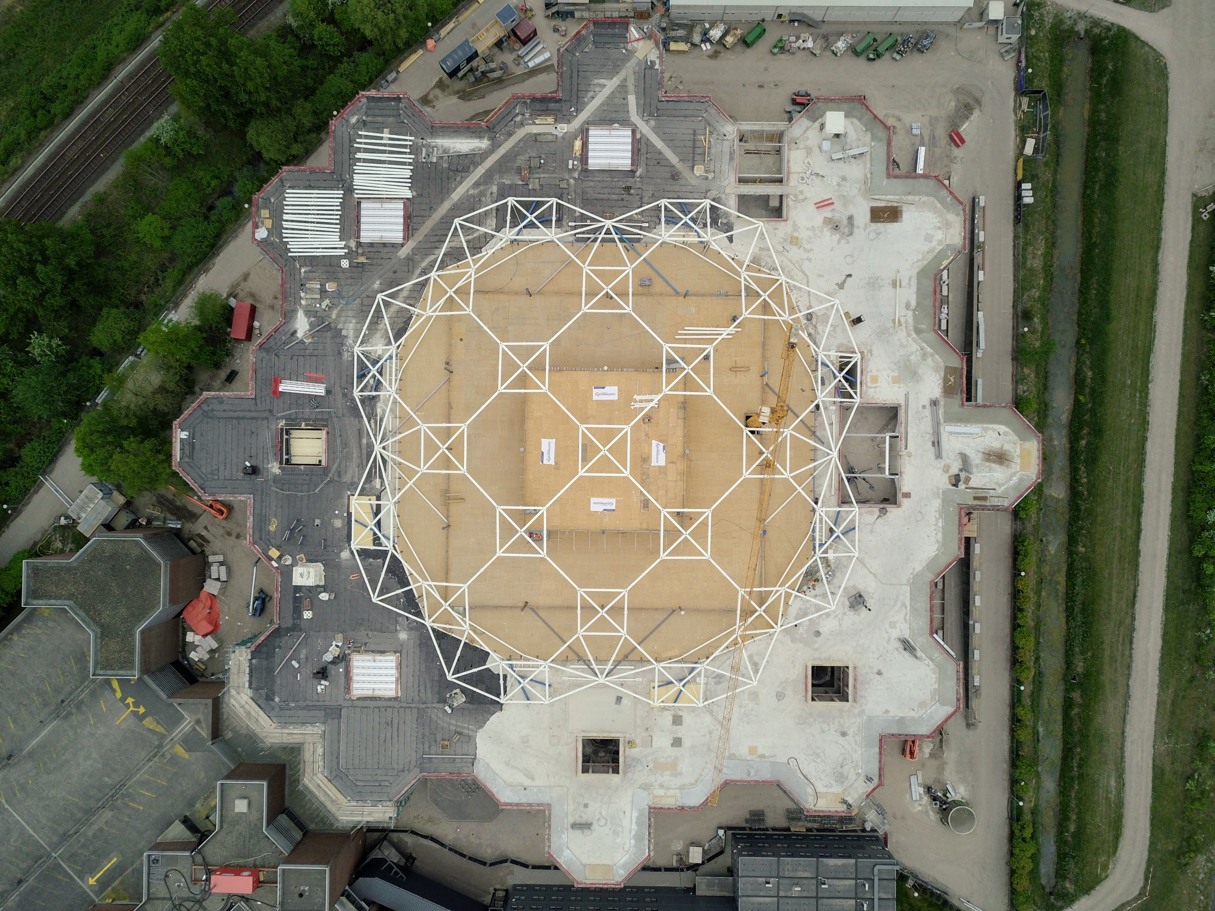
Figure 8: The dome under construction
To equally and incrementally pre-tension the structure, a crosswise bolt tightening order is used using steps of approximately six millimeters. After every cycle, the structure is measured at multiple points and compared to the pre-construction analysis. The torque in the bolts is also measured to determine the actual pre-tension force.
The steel dome structure with a free span of 76 meters was figured out efficiently and timely and only took eight weeks to construct.