Moment-Resisting Column-Base Connections in Glued Laminated Timber Using Glued-in Rods
Glued-in rod connections in laminated timber are often used in areas prone to earthquakes due to their ability to deform in a ductile manner. However, this connection could, in theory, also be used for different infrastructure purposes, such as road signs over highways, traffic lights, or railway catenaries. These objects are now made of either steel or aluminum but could potentially be replaced by to laminated timber. The goal of this research is to create a reliable prediction model for the ultimate moment capacity of said connection. This is done by investigating different failure mechanisms, determining the new position of the neutral axis due to the geometry of the cross-section, and verifying the model by experimental research.
The laminated beams with the glued-in rod connections and the smaller samples used in this research are provided by De Groot Vroomshoop. The samples consist of five different types amongst three categories of tests. Two of these categories are reserved for determining material properties, while the last category measures the rotational stiffness of the connection to determine the moment capacity, see Figure 1.
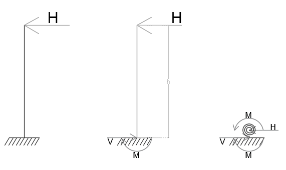
Figure 1: Mechanical scheme simplification
These moment-resistant connections are, in reality, subjected to wind which can come from all directions; the cross-section is thus symmetrical. To design the geometry, a literature review was done to find the optimal distances of the steel rods from the edges and the other bars, as well as bar diameters and glued-in depths [1] – [2].
The cross-section is subjected to bending at the connection; this means that the top part is in compression and the bottom part is in tension. The connection uses laminated timber, and the glued-in rods act as a composite material, with the steel acting in tension and the laminated timber in compression. Since different materials are present in the compressive and tensile part, the neutral axis is not located in the middle of the cross-section [3].
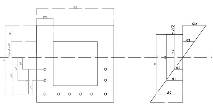
Figure 2: Analyical model starting assumptions
To predict the position of the neutral axis, an analytical model is created to determine the theoretical position and the corresponding moment capacity. This model is based on the failure mechanism where the steel is pulled out of the cross-section by failure of the timber and glue in the shearing plane along the rod. Due to the prescribed failure mechanism, the model stays within the limits of linear-elastic behavior. The cross-section design reduces the possibility of other possible failure mechanisms occurring.
The experimental research provides more clarity on certain parameters used in the model, such as the pull-out strength of the glued-in rod in the timber and the elastic modulus of the laminated timber. Finally, the rotational stiffness is measured to find the moment resistance of the cross-section and compare it to the analytical model.
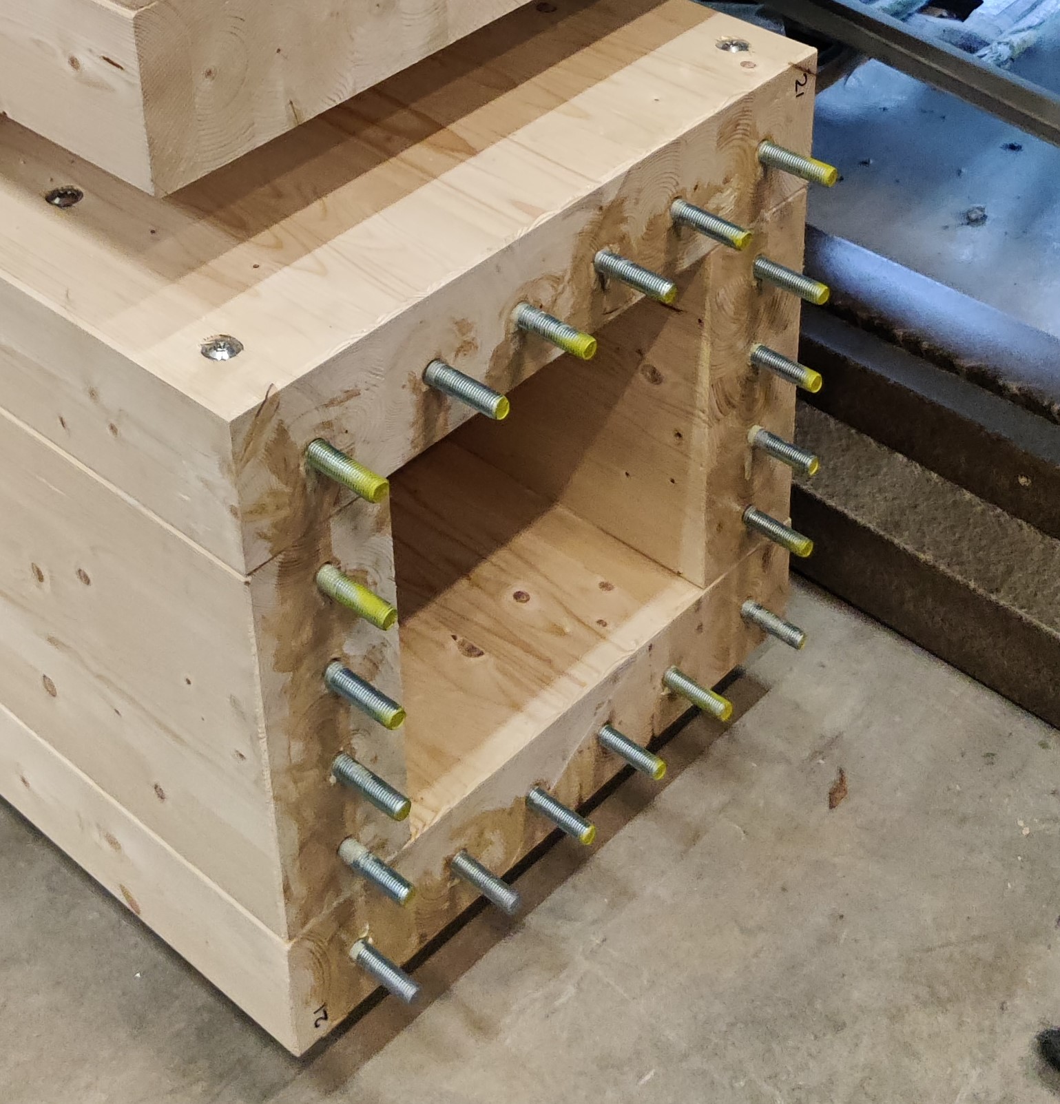
Figure 2: Analyical model starting assumptions
After this verification, the analytical model can be used to predict the moment capacity of this connection, allowing it to be an alternative to its metal counterparts.
References:
- Tlustochowicz, Gabriela, Erik Serrano, and René Steiger (2011). “State-of-the-art review on timber connections with glued-in steel rods”. In: Materials and Structures/Materiaux et Constructions 44.5, pp. 997–1020. issn: 13595997. doi: 10.1617/s11527-010-9682-9.
- Steiger, R, E Gehri, and R Widmann (2007). “Pull-out strength of axially loaded steel rods bonded in glulam parallel to the grain”. In: Materials and Structures/Materiaux et Constructions 40.1, pp. 69–78. issn: 13595997. doi: 10.1617/s11527-006-9111-2.
- Xu, B. H., A. Bouchaïr, and P. Racher (2012). “Analytical study and finite element modelling of timber connections with glued-in rods in bending”. In: Construction and Building Materials 34, pp. 337–345. issn: 09500618. doi: 10.1016/j. conbuildmat.2012.02.087.