Geotechnical Risk Management - Boerenwetering garage Amsterdam
In order to improve the quality of life and reduce parking problems in the “Oude Pijp” in Amsterdam, the underground parking garage the Boerenwetering is constructed. This underground parking lot has a capacity of 600 parking places. As a result, it is possible to reduce the number of parking places on the street by about 300. This is favourable for the pedestrians, cyclists, and the neighbourhood in general.
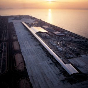
The header shows an impression of the Boerenwetering garage. The garage is constructed beneath/in the existing canal between the Hobbemakade and the Ruysdaelkade, close to the Rijksmuseum. The garage consists of two parking layers on top of which the canal will be reestablished.
The parking garage Boerenwetering is constructed withina deep excavation, enclosed by sheet pile walls. The length of this large pit is about 260 meters and the width is 30 meters. The sheet pile walls are also part of the permanent retaining walls of the parking garage. The building pit is constructed with one layer of struts and an underwater concrete floor. The underwater concrete floor is anchored with GEWI-anchors, which are applied vibration-free in order to minimise the hindrance for the surroundings. The distance between the sheet pile walls and the buildings at the Hobbemakade is about 20 meters, while the distance between the building pit and the buildings along the Ruysdaelkade is 8 to 9 meters.
Soil profile and groundwater
The surface level at the project location is NAP +0.5 meters. The soil is a typical Amsterdam soil profile. In other words, the top layer consists of anthropogenic sand. This is followed by Holocene deposits, i.e. peat, clay, a tidal silty sand and clay layer, and the basal peat layer. Below the Holocene deposits, the first Pleistocene sand layer is found at a depth around NAP -12 meters. The phreatic water level is NAP -0.4 meters, which is equal to the level in the canal. The piezometric level in the first Pleistocene sand layer is NAP -2.5 meters.
Geotechnical Risk Management
The lessons of Geotechnical Risk Management (GeoRM) are applied to minimize the risks of damage on existing and new structures in this project. GeoRM is one of the results of the comprehensive Dutch Geo-Impuls program for reducing geotechnical failure by 50% (2009-2014). The following approach was followed:
1. Determine the structural and foundation conditions and resistance of adjacent structures. Requirements are imposed by the nearby structures and various parties, such as building owners or service companies.
2. Predicting deformations, vibrations, and groundwater level changes due to construction works.
3. Determine the expected damage risks; relate steps 1 and 2.
4. Take preventive (design) measures when requirements are not met. This will lead to a final design that meets the criteria. A monitoring program is defined to check whether these criteria are also met during construction.
5. Monitoring; compare prediction with measurements during execution (observational) in each relevant construction phase.
6. Take correction measures when measurements exceed the prediction. Define the measures in the design process. These six steps are incorporated in the complete design process for the parking garage Boerenwetering.
Risk assessment - vibrations
Two main sources of vibrations are defined in this project; vibrations caused by vibrating the sheet pile walls into the ground and vibrations caused by passing construction vehicles.
CRUX has taken the following systematic steps to determine possible damage to surrounding buildings due to vibrations:
• Predict vibration intensity at the location of nearby buildings due to installation of the sheet pile walls (in accordance with the calculation procedure described in CUR166 3rd edition);
• Conduct a vibration test of passing (construction) vehicles, before the construction works and during the construction works;
• Check the vibration intensities to the Dutch guideline SBR-A (for damage to buildings).
The vibration measurements prior to the start of construction show that the SBR criteria are met in the initial state. When this would not be the case or when limit values are exceeded during construction, the most effective correction measures are a speed reduction and/or levelling of the pavement. Predictions of the vibration levels during the installation of the sheet pile walls show that the sheet pile walls can be vibrated into the ground at the (side of the) Hobbemakade, where the distance between the buildings and the pit is relatively large. At the (side of the) Ruysdaelkade, however, this distance is too small, which led to the choice for the press-in method. Monitoring during construction proved that the prediction was correct.
Building pit design
Sheet pile walls
Two different types of sheet pile walls are used during construction of the building pit. Along the Ruysdaelkade, AZ 26-700N profiles are used, which are pressed into the soil (Figure 1). Due to this method, deformations and vibrations are minimized. Along the Hobbemakade and the short sides of building pit, AZ 18-700N profiles are vibrated into the soil. The earlier mentioned sheet piles are placed 1 meter into the first Pleistocene sand layer, i.e. installed at NAP -13.5 meters to -14.0 meters.
The excavation depth within the building pit is NAP -10.6 meters. In order to ensure stability of the building pit during excavation, a layer of struts is placed at a depth of NAP -2.5 meters. These struts are placed under water using divers. This means that the first 3 meters are excavated without support. The deformation of unsupported sheet pile walls is relatively difficult to predict as they are sensitive to a change in load and/or support. At the Ruysdaelkade in particular, this means that a load restriction is set on surface level. Too much deformation in this phase will result in additional deformation in the deepest excavation stages. Therefore, it is of importance to control the deformation in the early excavation stages. To control the deformation, two measures are taken:
1. A stiffer sheet pile wall is applied at the Ruysdaelkade side.
2. The struts can be prestressed when they are positioned. Whether the struts will actually be prestressed, will be decided based on the monitoring data (observational method).
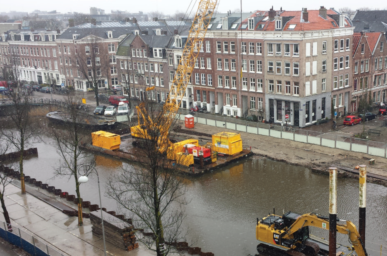
Figure 1: Installation of sheet pile walls at the Ruysdaelkade
Underwater concrete floor
The excavation of the building pit is a so-called wet excavation. This construction method is also favourable regarding deformations. The largest part of the load that a sheet pile wall has to resist originates from the difference in water level. During the wet excavation stages, there is no difference in water level. Once the underwater concrete floor is installed, the sheet pile wall will be supported at two levels in a structurally favourable way, minimising the deflection of the wall when it is fully loaded. Another advantage is that the risk of influencing the water levels outside the building pit is minimized because the water is drained from the pit once both a vertical and horizontal barrier is in place.
The underwater concrete floor is 0.9 meter thick and lies on a 0.3 meter thick gravel layer. The gravel layer contributes to a potential control of the upward water pressure beneath the underwater concrete floor. The larger part of the upward water pressure is counterbalanced by GEWIanchors.
Struts
The struts are constructed from 1,020 x 15 millimeters tubes with 5.32 meters spacing (Figure 2). Normally, the struts are not prestressed. The necessity of prestressing follows from the risk assessment. Prestressing is necessary when the limit value for deformations of the sheet pile wall is reached in the first excavation phase. When the limit value is reached, a prestress force up to 250 kN/m can be applied.
The building pit was designed in close cooperation with all parties involved in the pit construction. Involvement in an early stage of all parties is a risk measure in itself. Issues that are solved in the ‘construction pit team’ are (among others):
• Relation between columns, pile grid, and strut center to center distance;
• Effect of a change in pile loads (tension to pressure load) in relation to the pile grid;
• Fibers added to the underwater concrete in relation to reinforcement cages in the underwater concrete;
• Tolerances in the struts in relation to the installation of sheet pile walls and known obstacles.
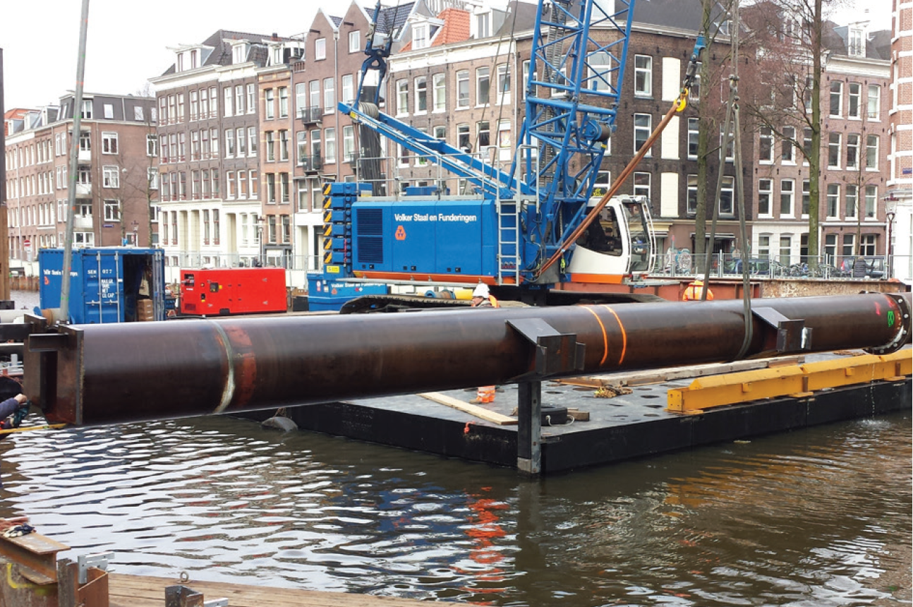
Figure 2: Placing the struts
Deformations
The main source of ground deformation is the deflection of the sheet pile wall during excavation. The deformation due to excavation of the building pit are predicted with the finite element (FE) software PLAXIS. Figure 3 shows an example of the model used. The damage assessment of the design, in order to arrive at a final design, was performed using the Tensile limiting strain method by Netzel (2009).
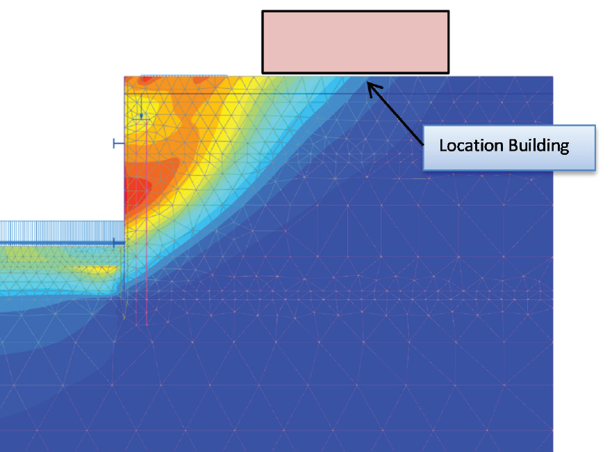
Figure 3: Impression of the deformation contours calculated in PLAXIS in the final excavation phase
Monitoring
The objective of monitoring during construction is to gather monitoring data in different construction phases, with respect to developments in deformations, vibrations, sound levels, air quality, and ground water level changes in and around the construction site. Monitoring enables the possibility to anticipate when the measurement data is likely to exceed the previously determined limit values. Monitoring plan In this project, the following aspects are monitored:
• Deformation of the surrounding objects; Objects surrounding the site include: buildings, bridges, sewer pipes and the quay walls along the Hobbemakade and the Ruysdaelkade. Deformations of these objects are measured by precise levelling on measuring bolts attached to the buildings and bridges (see Figure 4).
• Monitoring of cracks in surrounding buildings; In case there are cracks on the surrounding buildings and bridges, prior to the construction, crack gauges are placed to monitor movements in the cracks.
• Horizontal deformations of the sheet pile walls; Deformations of the sheet pile walls are measured with inclinometers and with x,y,z measurements of the top of the wall (see Figure 4).
• Vibrations on surrounding buildings; As discussed before.
• Water levels; The water levels are measured with stand pipes in the surrounding area. All three piezometric levels are monitored: the phreatic level, the tidal sand deposit level and the first sand layer.
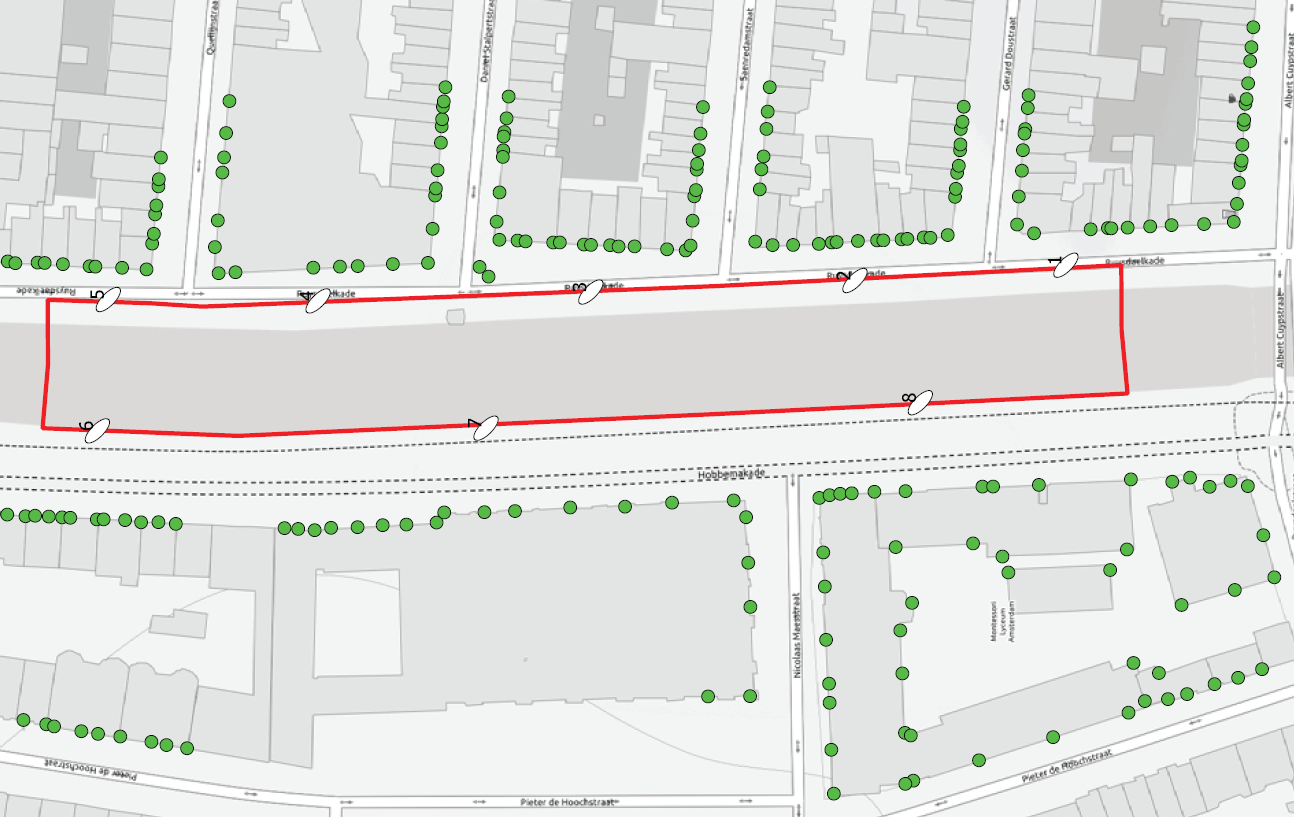
Figure 4: Impression of the number of precise levelling points around the Boerenwetering garage
Status of execution
At the moment of writing this article, the struts are in place and deep excavation has just started. Monitoring has shown that the deflection of the sheet pile wall and also the deformation of the building are within the predicted limits. This means that prestressing is not necessary. The Boerenwetering garage is expected to open to the public at the end of 2017.
Figures:
Header, 1-4 CRUX Engineering BV & Max Bögl Nederland BV