Challises on a Tunnel Roof
In 2018 a new bus station structure was built in Leidsche Rijn Utrecht. This had to be a lightweight structure due to the tunnel structure underneath the station. This structure, consisting of a light steel frame with tensioned membranes, was designed as a Gothic cathedral.
Bus station Leidsche Rijn is located on top of the tunnels of the A2 motorway and the adjacent city tunnel. The load induced by buses and a possible future streetcar leaves little carrying capacity left for a roof structure above the bus station. Nevertheless, architect Annebregje Snijders of the architectural firm AnnA wanted to finish the Brusselplein, ending with a grand gesture. The bus station stands on the north side of this Brusselplein and connects to the previously placed restored historic hoods of train station Utrecht. Comparing the possibilities and considering the axes of the adjacent city center Leidsche Rijn, Snijders chose a triangular floor plan with columns in four parallel rows spaced at 17.5 meters. The longest row has four columns; for every next row, the length reduces by one column. The structure is hexagonal and consists of copper-colored steel tube profiles.
Steel and membrane collaboration
Snijders contacted us, and our first reaction was: ‘Do you really want this?’ We had previously been involved in reconstructing the historic station roofs and thus knew the structural possibilities of the tunnel box. Together, we then took up the principal engineering. After this was done, the work was put out to tender, and Buiting Steel Construction and BuitinkTechnology together with Tentech did the further detailed engineering. Project Leader Structures Diana de Krom: “The advantage of this engineering in advance is that you can use the collaboration between steel and the membranes in one calculation model. Usually, these are calculated separately; however, the steel structure could be slightly lighter due to the combination.’’ This collaboration is illustrated in Figure 1.
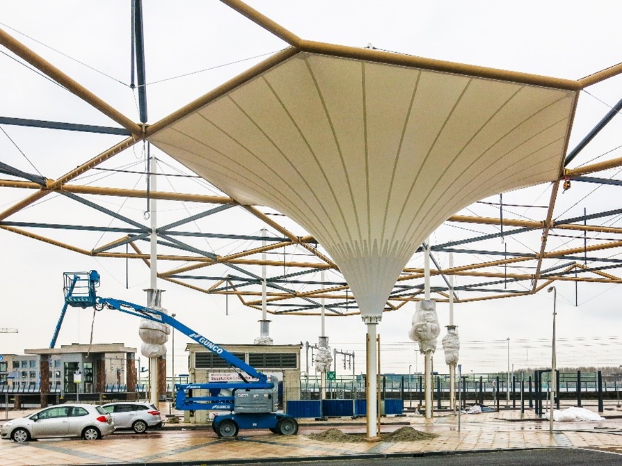
Figure 1: Construction of the bus station
Wind loading
On the tunnel roof is a soil package of only one meter, which leaves little room for constraining. The ten columns of the roof structure rest on three by three meter spanning slabs with a thickness of 150 millimeters, ensuring the load is spreading on the tunnel roof. Diana de Krom: “A canopy always tends to have uplift. Compensation is possible with tension anchors or weighted foundation plates. Tension anchors are not possible on the tunnel roof, and increasing the load of the foundation is also not possible. The shape of the chalices is so specific that the standard does not prescribe how the wind load should be calculated. We expected that these challises would not be pushed up by wind, but we needed to check this. We considered wind tunnel research to prove it, but this took time and was expensive. Ultimately, we opted for CFD simulation (Computational Fluid Design), which is usually used to visualize wind nuisance. This simulation showed that the canopy was indeed not going to blow up.’’ The coupling between columns and concrete takes place below ground level so that the columns protrude tightly and slenderly from the platforms. Because the bus station rests on two tunnels, the construction is not coupled at ground level. However, at the 11-meter-high roof level, this was allowed. The columns are wedged into the concrete slabs for stability, while the membrane, by its shape and interconnection, also contributes to the stability.
Connections
Copper-colored steel tube profiles form the main structure of the hexagons. These are suspended with tie rods from the ornately designed tops of the columns. Horizontal steel box sections around the columns fix the hexagons in the horizontal direction. The various tubes are not welded but are connected with tube-in-tube structures connected and bolted together. End plates have been added at the junctions and bolted together. For the engineering of the nodes, the assembly sequence was also essential to fit the tube sections of the hexagons in the correct order. This was also true for the membrane structure: it was already pre-attached to the columns in advance. Because of the steel structure above, retrofitting was not an option. After mounting the steel, the membranes were suspended at the top and tensioned at the bottom. The structure was made such that tensioning remains possible.
Triangles
The remaining triangles between the hexagons are sealed with a secondary membrane structure, which is pushed up with a pre-tensioned mast at its center. The electricity supply cable passes through the columns and is routed along the tension wires. The membranes of these triangles are attached to the top of the steel structure so that rainwater drains into the chalice structures. Along the edges of the bus station, the remaining triangles are executed with a triangular curb in the eaves. An upper steel tube profile serves as a brace to hold the curb in the eaves in place.
Snow load
A snow load, according to the standards, was not a problem. However, the municipality of Utrecht wanted to increase the safety and wanted to know what would happen if the challises were unexpectedly filled with snow. We made the calculation and found that the membranes would bulge but not rupture. This bulging is a warning mechanism that guarantees safety.
Engineering process
The stability of the structure is provided by the entrapment of the columns in the concrete piers. The wind load is transmitted as a transverse force through the columns to the foundation. The cables and diaphragms thereby have a stiffening effect on the horizontal displacement of the structure. In fact, when the structure is displaced horizontally, the angle of the diamond-shaped geometry created by the membranes and cables changes. The cables and membranes counteract this shape change, thereby counteracting the horizontal displacement. The flow of forces is illustrated in Figure 2.
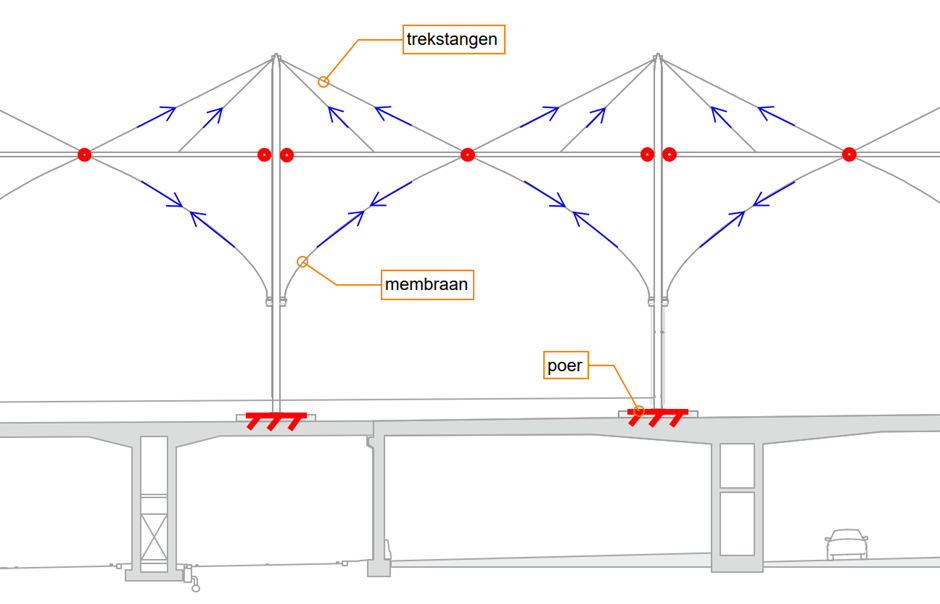
Figure 2: Flow of forces
In order to get the correct shape of the membrane in the calculation model, form-finding was applied, where the calculation model looks for the double-curved shape that the membrane assumes under the prescribed radial and tangential preload. A nonlinear geometric calculation was then performed for the various load combinations of self-weight, preload, wind, and snow loads. Finally, the strength and stability tests of the steel profiles, cables, and membranes were performed in the calculation package. The model is illustrated in Figure 3.
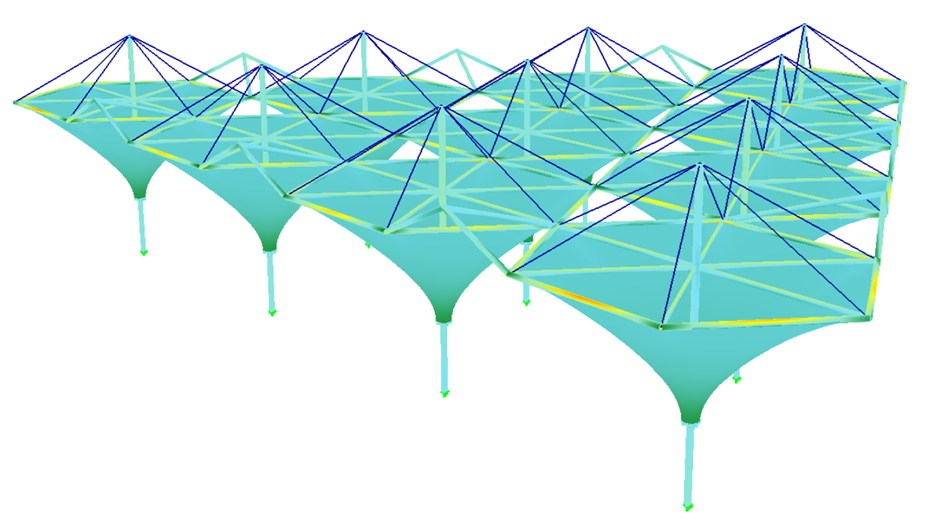
Figure 3: Calculation model