Master Thesis of Jelle Versteege
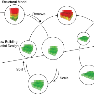
One of the main advantages of additive manufacturing, or more specifi cally 3D concrete printing (3DCP), is that such methods are capable of fabricating non-standard shapes at no extra cost or environmental impact. This quality opens up possibilities for practical applications of structural optimization within the building industry, as the complex shapes that result from these optimizations are no longer restrained by the conventional manufacturing methods. The graduation research presented in this article aimed to create a computational procedure that uses topology optimization to optimize a given geometry structurally and subsequently generate at least one viable print within the resulting optimized structure. This approach allows the strengths of additive manufacturing and topology optimization to be combined, while simultaneously reducing the required amount of manual post-processing signifi cantly. In this way, topology optimization becomes a more viable option beyond just the conceptual design stage, and the complex shapes allow the 3D concrete printer to be used to its full potential.
There are two main problems regarding this procedure, both of which need to be addressed consecutively by the algorithm. First of all, the structural optimization must accurately follow the structural behavior of 3DCP structures, otherwise the resulting geometries are not usable in practice. Secondly, in order to generate suitable print paths within these geometries, the algorithm should adhere to certain restrictions. Three restrictions have been defined based on the limitations of current state-of-the-art concrete printers, primarily to ensure that the use of this algorithm is not limited to a single printer.
The emphasis of this research lies on extrusion-based 3DCP with the automated insertion of cable reinforcement. In this way, the whole manufacturing process is automated, while the reinforcement cable still provides tensile strength to the structure. In order to model the material behavior of cable-reinforced concrete, two assumptions were made to simplify the problem. It is assumed that the direction of the reinforcement cable is consistently aligned with the major principal stress, denoted as σ1. Additionally, the reinforcement is not evaluated as individual cables; it is assumed to be distributed finely and evenly over the material, changing the reinforcement into a property of the material rather than a geometrical feature. With these assumptions taken into account, it is possible to incorporate the structural behavior of the cable into the yield criterion of concrete. The yield criterion is now based on the behavior of uncracked concrete, the tensile capacity of the cable reinforcement and the behavior of the cracked concrete perpendicular to the cables. A theoretical yield criterion was found by combining several theories and experiments, as depicted in Figure 1. The criterion primarily follows the modified Mohr-Coulomb theory, with the exception of the expansion in the region of uniaxial tension. Due to the nature of this approach, only stress analysis is required for the topology optimization to function, and the lack of complex reinforcement models keeps the optimization loop relatively simple.

Figure 1: The yield criterion for cable-reinforced concrete
The implementation of reinforcement does not only influence the strength of the material, it also makes non-linear material behavior unavoidable. Therefore, a non-linear stress-strain relationship is implemented in order to improve the accuracy of the structural analysis. The relationship is based on experimental research of reinforced concrete in tension; once the tensile strength of the concrete is reached, the stiffness of the material is greatly reduced. Additionally, yield plateaus are implemented at the compressive and tensile strength of the material. Depending on the case study, this non-linear behavior can significantly impact the final result of the topology optimization.
Because of the implementation of the yield criterion with reinforcement and the non-linear stress-strain relationship, it can be stated that the behavior of reinforced concrete is properly predicted. In other words, if this structural analysis is used within a topology optimization algorithm, it will result in shapes that are optimized for reinforced concrete. Therefore, the results are suitable as a base for the print path generation. In order to illustrate the results of the optimization, a case study has been set up. The structure can be best described as a cantilevering high beam, with a 3 meter length, a height of 1 meter and 0,2 meter wide, meshed into 240 by 80 elements. A load of 120 kN has been placed at the end (Figure 2).
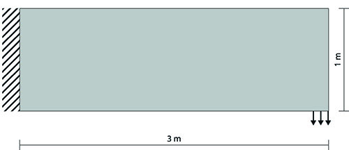
Figure 2: The cantilevering high beam used in the case study
A well-known sensitivity-based compliance optimization is used to find the topology optimization solution for this case study. At first sight, it might seem counter-intuitive to optimize the compliance (stiffness) of the structure. The goal is to make topology optimization viable beyond the conceptual design stage. Therefore, it can be stated that stress optimization, where the structure is optimized to satisfy the stress limits of the material, should be used instead. However, due to the implementation of the yield plateaus in the stress-strain relationship, there is a significant loss of stiffness for the material once the stress limit is exceeded. Consequently, stress values beyond the limit become highly unfeasible for compliance optimization as well; the structure is indirectly optimized to satisfy the stress limits of the material. In addition, using compliance optimization has the added benefit that such methods can have a high mathematical rigor with relative ease, preventing local optima, and naturally the resulting structure will have a high stiffness. If the case study result from this topology optimization algorithm is analyzed, as displayed in Figure 3, it can easily be noted that the members loaded in compression (red) are more slender than the members loaded in tension (blue). This is logical; the compressive strength of the reinforced concrete is higher than its tensile strength.
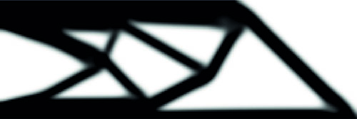
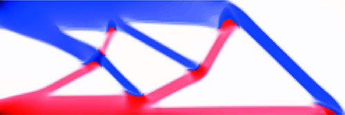
Figure 3a: The result of the topology optimization
Figure 3b: The corresponding stresses, blue is tension and red is compression
The next step in the computational procedure is to transfer the obtained result into a manufacturable geometry by generating a print path. As mentioned before, three restrictions are taken into account within the algorithm to make sure that the result can be printed in practice. First of all, the print path should follow a continuous path, with identical start and endpoints. This constraint ensures that the printer can start with the next layer uninterrupted. Secondly, the print path should not intersect itself. It is generally discouraged to intersect the print path during cable-reinforced printing, as it is highly unpredictable how the cables will behave when the path is crossed. Finally, for areas of cable-reinforced prints that are loaded in tension, the print path should follow the direction of the tensile stresses as closely as possible to satisfy the assumption that was made to set up the material model. Additionally, because computational time is ever an important factor, it was aspired to keep this to a minimum by abstracting the geometrical analysis to simple yet effective steps.
In the print path algorithm, a distinction is made between structural members and connections, i.e. the place where multiple members meet. First, the members are optimized, however, this is based on the assumption that the printer can vary the width of the path within a reasonable range during printing. Without this assumption, each geometry would only have a single layout of print paths, which would make finding a solution next to impossible. In the optimization, the member’s print paths are interpreted as a network of straight lines, also known as a graph, to simplify the analysis without losing crucial information. All possible combinations of print paths are analyzed. For each combination it is determined whether a continuous path is theoretically possible or not. Due to the simplified analysis, this generally only takes seconds. Depending on the case study, this non-linear behavior can significantly impact the final result of the topology optimization.
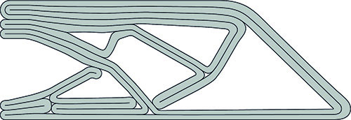
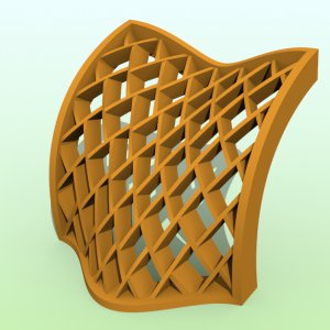
Figure 4: The final results of the algorithm, one continuous print path
Next, the connections are filled in, connecting the print paths in the members and therefore creating a full print path. At this point in the algorithm, two of the print path restrictions are satisfied. First, all intersecting connection layouts are filtered out by comparing them to a database of all possible non-intersecting intersections. Subsequently, intersecting paths are prevented in the geometry. Additionally, the flow of forces is determined within each connection. For each non-intersection connection, the layout is determent based on how paths can accurately follow the tensile stresses. All poor performing connections are eliminated. At this point, all that is left is to find the continuous path, which is achieved by generating and checking combinations of connections. The analysis is once more highly simplified, this time to a set of points, and in this way the algorithm can check tens of thousands of combinations per second. By checking a large number of combinations, there is a large chance that at least one continuous path is found. The result is a print path that requires very little post-processing, as seen in Figure 4. In this way, the potential of structural optimization is brought beyond just the conceptual design phase through the use of 3DCP.
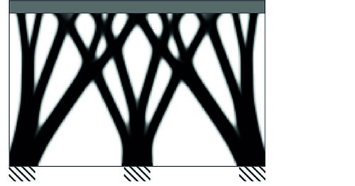
Figure 5: The topology optimization result of the shear wall case study
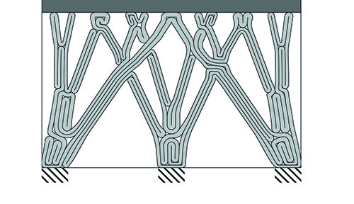
Figure 6: The print path solution of the shear wall cases study
For illustrative purposes the procedure has run once more, this time with a more practical case study (Figure 5 and Figure 6). The aim is to optimize a shear wall, a very common practical application of reinforced concrete. The wall is 4 meter wide and 2,4 meter high, and it supports a floor slab. Three load cases are applied; exclusively the dead load of the slab, the dead load of the slab combined with a horizontal displacement of the slab due to wind, and a similar load case with the wind load mirrored. Due to the nature of these load cases, nearly the entire structure is constantly subject to compressive stresses, and therefore only the non-intersecting continuous path is of importance. While this result does not show the inner workings of the algorithm as clearly as the cantilever does, it does provide a clear illustration of how optimized reinforced concrete structures could look in practice.